- Table of Contents
- Related Documents
-
| Title | Size | Download |
|---|---|---|
| 01-QoS Configuration | 660.05 KB |
Table of Contents
Traditional Packet Forwarding Service
New Requirements from New Services
Congestion: Causes, Impacts, and Countermeasures
Major Traffic Management Techniques
2 Traffic Policing, Traffic Shaping, and Line Rate Configuration
Traffic Policing, Traffic Shaping, and Line Rate Overview
Traffic Evaluation and the Token Bucket
Evaluating the traffic with the token bucket
Line Rate Configuration Procedure
Displaying and Maintaining Line Rate/GTS
Policy-Based Routing Configuration
Configuring Policy-Based Routing
Policy-Based Routing Configuration Examples
Displaying and Maintaining QoS Policies
Displaying and Maintaining Congestion Management
Traditional packet drop policy
Displaying and Maintaining WRED
Configuring a Priority Mapping Table
Configuring Port Priority Trust Mode
Displaying and Maintaining Priority Mapping
QoS Functions for Uplink Traffic
QoS Functions for Downlink Traffic
Configuring QoS in an EPON System
QoS Configuration Task List in an EPON System
Configuring QoS at the OLT side
Configuring QoS at the ONU Side
Example for UNI Priority Remarking Configuration
1 QoS Overview
This chapter covers these topics:
l Traditional Packet Forwarding Service
l New Requirements from New Services
l Congestion: Causes, Impacts, and Countermeasures
l Major Traffic Management Techniques
Introduction
In an internet, QoS refers to the ability of the network to forward packets. The evaluation on QoS of a network can be based on different aspects because the network may provide various services. Generally, QoS refers to the ability to provide improved service by solving the core issues such as delay, jitter, and packet loss ratio in the packet forwarding process.
Traditional Packet Forwarding Service
On traditional IP networks, devices treat all packets equally and handle them using the first in first out (FIFO) policy. All packets share the resources of the network and devices. How many resources the packets can obtain completely depends on the time they arrive. This service is called best-effort. It delivers packets to their destinations as possibly as it can, without any guarantee for delay, jitter, packet loss ratio, reliability and so on.
This service policy is only suitable for applications insensitive to bandwidth and delay, such as WWW, file transfer and e-mail.
New Requirements from New Services
The Internet has been growing along with the fast development of networking technologies. More and more users take the Internet as their data transmission platform to implement various applications.
Besides traditional applications such as WWW, e-mail and FTP, network users are experiencing new services, such as tele-education, telemedicine, video telephone, videoconference and Video-on-Demand (VoD). The enterprise users expect to connect their regional branches together through VPN technologies to carry out operational applications, for instance, to access the database of the company or to monitor remote devices through Telnet.
These new applications have one thing in common, that is, they all have special requirements for bandwidth, delay, and jitter. For instance, videoconference and VoD need large bandwidth, low delay and jitter. As for mission-critical applications, such as transactions and Telnet, they may not require large bandwidth but do require low delay and preferential service during congestion.
The new emerging applications demand higher service performance of IP networks. Better network services during packets forwarding are required, such as providing dedicated bandwidth, reducing packet loss ratio, managing and avoiding congestion, regulating network traffic, and setting the precedence of packets. To meet these requirements, networks must provide more improved services.
Congestion: Causes, Impacts, and Countermeasures
Network congestion is a key factor to degrade the service quality of a traditional network. Congestion refers to the fact that the forwarding rates are decreased due to insufficient resources, resulting in extra delay.
Causes
Congestion easily occurs in complex packet switching circumstances in the Internet. The following figure shows two common cases:
Figure 1-1 Traffic congestion causes

l The traffic enters a device from a high speed link and is forwarded over a low speed link;
l The packet flows enter a device from several interfaces with the same speed and are forwarded through an interface with the same speed as well.
When traffic arrives at the line speed, congestion may occur due to the network resource bottleneck.
Besides the link bandwidth bottleneck, congestion can also be caused by resource shortage, such as insufficient processor time, buffer, and memory. In addition, congestion may occur if the arriving traffic is not managed efficiently, thus resulting in inadequate network resources.
Impacts
Congestion may cause the following negative effects:
l Increasing the delay and jitter during packet transmission
l Decreasing network throughput and resource utilization
l Occupying too many network resources (memory in particular) and even leading to system breakdown
It is obvious that congestion makes traffic unable to obtain resources in time and degrades service performance. Congestion occurs frequently in complex environments where packet switching and multi-user applications coexist, and therefore needs to be treated cautiously.
Countermeasures
A simple solution for congestion is to increase network bandwidth. However, it cannot solve all the problems that cause congestion.
A more effective solution is to provide differentiated services for different applications through traffic control and resource allocation. In this way, resources can be used more properly. During resources allocation and traffic control, the direct or indirect factors that might cause network congestion should be controlled to reduce the probability of congestion. Once congestion occurs, resource allocation should be performed according to the characteristics and demands of applications to minimize the effects of congestion on QoS.
Major Traffic Management Techniques
Figure 1-2 End-to-end QoS model
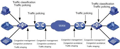
A shown in Figure 1-2, traffic classification, traffic policing, traffic shaping, congestion management, and congestion avoidance are the foundations for a network to provide differentiated services. Mainly they implement the following functions:
l Traffic classification uses certain match criteria to organize packets with different characteristics into different classes, and is the prerequisite for providing differentiated services. Traffic classification is usually applied in the inbound direction of a port.
l Traffic policing polices particular flows entering a device according to configured specifications and is usually applied in the inbound direction of a port. When a flow exceeds the specification, some restriction or punishment measures can be taken to prevent overconsumption of network resources and protect the commercial benefits of the carrier.
l Traffic shaping proactively adjusts the output rate of traffic to adapt traffic to the network resources of the downstream device and avoid unnecessary packet drop and congestion. Traffic shaping is usually applied in the outbound direction of a port.
l Congestion management provides measures for handling resource competition during network congestion and is usually applied in the outbound direction of a port. Generally, it stores packets in queues, and then uses a scheduling algorithm to arrange the forwarding sequence of the packets.
l Congestion avoidance monitors the usage status of network resources and is usually applied in the outbound direction of a port. As congestion becomes worse, it actively reduces the amount of traffic by dropping packets.
Among these traffic management technologies, traffic classification is the basis for providing differentiated services by classifying packets with certain match criteria. Traffic policing, traffic shaping, congestion management, and congestion avoidance manage network traffic and resources in different ways to realize differentiated services.
Traffic classification organizes packets with different characteristics into different classes using match criteria. It is the basis for providing differentiated services.
You can define match criteria based on the IP precedence bits in the type of service (ToS) field of the IP packet header, or based on other header information such as IP addresses, MAC addresses, IP protocol field, and port numbers. Contents other than the header information in packets are rarely used for traffic classification. You can define a class for packets with a common quintuple (source address, source port number, protocol number, destination address and destination port number), or for all packets to a certain network segment.
When packets are classified at network boundaries, the precedence bits in the ToS field of the IP packet header are generally re-set. In this way, IP precedence can be adopted as a classification criterion for the packets in the network. IP precedence can also be used in queuing to prioritize traffic. The downstream network can either inherit the classification results from its upstream network or re-classify the packets according to its own criteria.
To provide differentiated services, traffic classes must be associated with certain traffic control actions or resource allocation actions. What traffic control actions should be adopted depends on the current phase and the resources of the network. For example, CIR is adopted to police packets when they enter the network; GTS is performed on packets when they flow out of the node; queue scheduling is performed when congestion happens; congestion avoidance measures are taken when the congestion deteriorates.
When configuring traffic policing, and line rate, go to these section for information you are interested in:
l Traffic Policing, Traffic Shaping, and Line Rate Overview
l Traffic Evaluation and the Token Bucket
l Displaying and Maintaining Line Rate/GTS
Traffic Policing, Traffic Shaping, and Line Rate Overview
If the traffic from users is not limited, a large amount of continuous burst packets will result in worse network congestion. The traffic of users must be limited in order to make better use of the limited network resources and provide better service for more users. For example, if a traffic flow obtains only the resources committed to it within a certain period of time, network congestion due to excessive burst traffic can be avoided.
Traffic policing and traffic shaping are traffic control policies for limiting traffic and resource usage by supervising the traffic. The prerequisite for traffic policing and traffic shaping is to determine whether or not the traffic exceeds the set threshold. Traffic control policies are adopted only when the traffic exceeds the set threshold. Generally, token bucket is used for evaluating traffic.
Traffic Evaluation and the Token Bucket
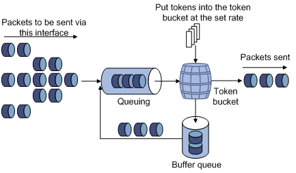
Token bucket
The token bucket can be considered as a container with a certain capacity to hold tokens. The system puts tokens into the bucket at the set rate. When the token bucket is full, the extra tokens will overflow and the number of tokens in the bucket stops increasing.
Figure 2-1 Evaluate the traffic with the token bucket
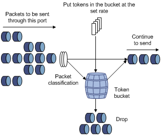
Evaluating the traffic with the token bucket
The evaluation for the traffic specification is based on whether the number of tokens in the bucket can meet the need of packet forwarding. If the number of tokens in the bucket is enough to forward the packets, the traffic is conforming to the specification; otherwise, the traffic is nonconforming or excess.
When the token bucket evaluates the traffic, its parameter configurations include:
l Average rate: The rate at which tokens are put into the bucket, namely, the permitted average rate of the traffic. It is generally set to committed information rate (CIR).
l Burst size: The capacity of the token bucket, namely, the maximum traffic size that is permitted in each burst. It is generally set to committed burst size (CBS). The set burst size must be greater than the maximum packet length.
An evaluation is performed on the arrival of each packet. In each evaluation, if the bucket has enough tokens for use, the traffic is controlled within the specification and a number of tokens equivalent to the packet forwarding authority must be taken out; otherwise, this means too many tokens have been used — the traffic is in excess of the specification.
Complicated evaluation
You can set two token buckets in order to evaluate more complicated conditions and implement more flexible regulation policies. For example, traffic policing uses four parameters:
l CIR
l CBS
l Peak information rate (PIR)
l Excess burst size (EBS)
Two token buckets are used in this evaluation. Their rates of putting tokens into the buckets are CIR and PIR respectively, and their sizes are CBS and EBS respectively (the two buckets are called C bucket and E bucket respectively for short), representing different permitted burst levels. In each evaluation, you can implement different regulation policies in different conditions, including “enough tokens in C bucket”, “insufficient tokens in C bucket but enough tokens in E bucket” and “insufficient tokens in both C bucket and E bucket”.
Traffic Policing
The typical application of traffic policing is to supervise the specification of certain traffic into the network and limit it within a reasonable range, or to "discipline" the extra traffic. In this way, the network resources and the interests of the operators are protected. For example, you can limit HTTP packets to be within 50% of the network bandwidth. If the traffic of a certain connection is excess, traffic policing can choose to drop the packets or to reset the priority of the packets.
Traffic policing is widely used in policing the traffic into the network of internet service providers (ISPs). Traffic policing can classify the policed traffic and perform pre-defined policing actions based on different evaluation results. These actions include:
l Forwarding conforming packets or non-conforming packets.
l Dropping conforming or non-conforming packets.
l Marking a conforming packet with a new 802.1p precedence value and forwarding the packet.
l Marking a conforming packet with a new IP precedence value and forwarding the packet.
l Marking a conforming packet or a non-conforming packet with a new DSCP precedence value and forwarding the packet.
Traffic Shaping
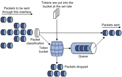
Traffic shaping provides measures to adjust the rate of outbound traffic actively. A typical traffic shaping application is to limit the local traffic output rate according to the downstream traffic policing parameters.
The difference between traffic policing and GTS is that packets to be dropped in traffic policing are cached in a buffer or queue in GTS, as shown in Figure 2-2. When there are enough tokens in the token bucket, these cached packets are sent at an even rate. Traffic shaping may result in an additional delay while traffic policing does not.
For example, in Figure 2-3, Switch A sends packets to Switch B. Switch B performs traffic policing on packets from Switch A and drops packets exceeding the limit.
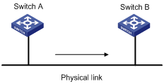
You can perform traffic shaping for the packets on the outgoing interface of Switch A to avoid unnecessary packet loss. Packets exceeding the limit are cached in Switch A. Once resources are released, traffic shaping takes out the cached packets and sends them out. In this way, all the traffic sent to Switch B conforms to the traffic specification defined in Switch B.
Line Rate
Port rate limiting refers to limiting the total rate of inbound or outbound packets on a port.
Port rate limiting can be implemented through token buckets. That is, if you perform port rate limiting configuration for a port, the token bucket determines the way to process the packets to be sent by this port or packets reaching the port. Packets can be sent or received if there are enough tokens in the token bucket; otherwise, packets are put into QoS queues for congestion management. In this way, the traffic passing the physical interface is controlled.
Figure 2-4 Line rate implementation
In the token bucket approach to traffic control, bursty traffic can be transmitted so long as enough tokens are available in the token bucket; if tokens are inadequate, packets cannot be transmitted until the required number of tokens are generated in the token bucket. Thus, traffic rate is restricted to the rate for generating tokens, thus limiting traffic rate and allowing bursty traffic.
Line rate can only limit the total traffic rate of a physical interface, while traffic policing limits traffic by flow. To limit the rate of all the packets on interfaces, using line rate is easier.
GTS/Line Rate Configuration
Configuring GTS
Configuration procedure
Follow these steps to configure GTS:
|
To do… |
Use the command… |
Remarks |
|
|
Enter system view |
system-view |
— |
|
|
Enter interface view or port group view |
Enter interface view |
interface interface-type interface-number |
Use either command Settings in interface view are effective on the current interface; settings in port group view are effective on all ports in the port group. |
|
Enter port group view |
port-group manual port-group-name |
||
|
Configure GTS for a queue |
qos gts queue queue-number cir committed-information-rate [ cbs committed-burst-size] |
Required |
|
GTS configuration example
Configure GTS on GigabitEthernet 2/0/1, shaping packets when the sending rate exceeds 640 kbps in queue 2.
# Enter system view.
<Sysname> system-view
# Enter interface view.
[Sysname] interface gigabitethernet 2/0/1
# Configure GTS parameters.
[Sysname-GigabitEthernet2/0/1] qos gts queue 2 cir 640
Line Rate Configuration Procedure
Configuration procedure
Follow these steps to configure line rate:
|
To do… |
Use the command… |
Remarks |
|
|
Enter system view |
system-view |
— |
|
|
Enter interface view or port group view |
Enter port view |
interface interface-type interface-number |
Enter either view. For Ethernet interface view, the following configuration takes effect only on the current interface. For entering port group view, the following configuration takes effect on all the ports. |
|
Enter port group view |
port-group manual port-group-name |
||
|
Configure line rate |
qos lr outbound cir committed-information-rate [ cbs committed-burst-size ] |
Required |
|
Line rate configuration examples
Limit the outbound rate of GigabitEthernet 2/0/1 to 640 kbps.
# Enter system view
<Sysname> system-view
# Enter interface view
[Sysname] interface GigabitEthernet 2/0/1
# Configure line rate parameter and limit the outbound rate to 640 kbps
[Sysname-GigabitEthernet2/0/1] qos lr outbound cir 640
Displaying and Maintaining Line Rate/GTS
|
To do… |
Use the command… |
Remarks |
|
Display the GTS configuration of interfaces |
display qos gts interface [ interface-type interface-number ] |
Available in any view |
|
Display the line rate configuration of interfaces |
display qos lr interface [ interface-type interface-number ] |
Available in any view |
When configuring QoS policy, go to these sections for information that you are interested in:
l Overview
l Policy-Based Routing Configuration
l Displaying and Maintaining QoS Policies
Overview
QoS policy includes the following three elements: class, traffic behavior and policy. You can bind the specified class to the specified traffic behavior through QoS policies to facilitate the QoS configuration.
Class
Class is used for identifying traffic.
The elements of a class include the class name and classification rules.
You can use commands to define a series of rules to classify packets. Additionally, you can use commands to define the relationship among classification rules: “and” and “or”.
l and: The devices considers a packet to be of a specific class when the packet matches all the specified classification rules.
l or: The device considers a packet be of a specific class when the packet matches one of the specified classification rules.
Traffic behavior
Traffic behavior is used to define all the QoS actions performed on packets.
The elements of a QoS behavior include traffic behavior name and actions defined in traffic behavior.
You can use commands to define multiple actions in a traffic behavior.
Policy
Policy is used to bind the specified class to the specified traffic behavior.
The elements of a policy include the policy name and the name of the classification-to-behavior binding.
Configuring a QoS Policy
The procedure for configuring QoS policy is as follows:
1) Define a class and define a group of traffic classification rules in class view.
2) Define a traffic behavior and define a group of QoS actions in traffic behavior view.
3) Define a policy and specify a traffic behavior corresponding to the class in policy view.
Configuration Prerequisites
Before configuring a QoS policy, identify the following:
l The name and rules of the class that the policy will reference.
l The name of the traffic behavior that the policy will reference and the actions to be defined in the traffic behavior.
l The policy name.
l The occasions where the policy is to be applied: on a port, port group, or VLAN, or in the global scope.
Defining a Class
To define a class, you need to create a class and then define rules in the corresponding class view.
Configuration procedure
Follow these steps to define a class:
|
To do… |
Use the command… |
Remarks |
|
Enter system view |
system-view |
— |
|
Create a class and enter the corresponding class view |
traffic classifier classifier-name [ operator { and | or } ] |
Required By default, the and keyword is specified. That is, the relation between the rules in the class view is logic AND. This operation leads you to class view. |
|
Define a rule used to match packets |
if-match match-criteria |
Required |
match-criteria: Matching rules to be defined for a class. Table 3-1 describes the available forms of this argument.
Table 3-1 The form of the match-criteria argument
|
Form |
Description |
|
acl access-list-number |
Specifies an ACL to match packets. The access-list-number argument is in the range 2000 to 4999. In a class configured with the operator and, the logical relationship between rules defined in the referenced IPv4 ACL is or. |
|
acl ipv6 access-list-number |
Specifies an IPv6 ACL to match IPv6 packets. The access-list-number argument is in the range 2000 to 3999. In a class configured with the operator and, the logical relationship between rules defined in the referenced IPv6 ACL is or. |
|
any |
Specifies to match all packets. |
|
customer-dot1p 8021p-list |
Specifies to match packets by 802.1p precedence of the customer network. The 8021p-list argument is a list of CoS values. You can provide up to eight space-separated CoS values for this argument. CoS is in the range 0 to 7. |
|
customer-vlan-id vlan-id-list |
Specifies to match the packets of specified VLANs of user networks. The vlan-id-list argument specifies a list of VLAN IDs, in the form of vlan-id to vlan-id or multiple discontinuous VLAN IDs (separated by space). You can specify up to eight VLAN IDs for this argument at a time. VLAN ID is in the range 1 to 4094. In a class configured with the operator and, the logical relationship between the customer VLAN IDs specified for the customer-vlan-id keyword is or. |
|
destination-mac mac-address |
Specifies to match the packets with a specified destination MAC address. |
|
dscp dscp-list |
Specifies to match packets by DSCP precedence. The dscp-list argument is a list of DSCP values. You can provide up to eight space-separated DSCP values for this argument. DSCP is in the range of 0 to 63. |
|
ip-precedence ip-precedence-list |
Specifies to match packets by IP precedence. The ip-precedence-list argument is a list of IP precedence values. You can provide up to eight space-separated IP precedence values for this argument. IP precedence is in the range 0 to 7. |
|
protocol protocol-name |
Specifies to match the packets of a specified protocol. The protocol-name argument can be IP or IPv6. |
|
service-dot1p 8021p-list |
Specifies to match packets by 802.1p precedence of the service provider network. The 8021p-list argument is a list of CoS values. You can provide up to eight space-separated CoS values for this argument. CoS is in the range 0 to 7. |
|
service-vlan-id vlan-id-list |
Specifies to match the packets of the VLANs of the operator’s network. The vlan-id-list argument is a list of VLAN IDs, in the form of vlan-id to vlan-id or multiple discontinuous VLAN IDs (separated by space). You can specify up to eight VLAN IDs for this argument at a time. VLAN ID is in the range of 1 to 4094. In a class configured with the operator and, the logical relationship between the service VLAN IDs specified for the service-vlan-id keyword is or. |
|
source-mac mac-address |
Specifies to match the packets with a specified source MAC address. |
![]()
Suppose the logical relationship between classification rules is and. Note the following when using the if-match command to define matching rules.
l If multiple matching rules with the acl or acl ipv6 keyword specified are defined in a class, the actual logical relationship between these rules is or when the policy is applied.
l If multiple matching rules with the customer-vlan-id or service-vlan-id keyword specified are defined in a class, the actual logical relationship between these rules is or.
Configuration example
1) Network requirements
Configure a class named test to match the packets with their IP precedence being 6.
2) Configuration procedure
# Enter system view.
<Sysname> system-view
# Create the class. (This operation leads you to class view.)
[Sysname] traffic classifier test
# Define the classification rule.
[Sysname-classifier-test] if-match ip-precedence 6
Defining a Traffic Behavior
To define a traffic behavior, you need to create a traffic behavior and then configure attributes for it in traffic behavior view.
Configuration procedure
Follow these steps to define a traffic behavior:
|
To do… |
Use the command… |
Remarks |
|
Enter system view |
system-view |
— |
|
Create a traffic behavior and enter the corresponding traffic behavior view |
traffic behavior behavior-name |
Required behavior-name: Behavior name. This operation leads you to traffic behavior view |
|
Configure accounting action |
accounting |
Required You can configure the traffic behavior as required. |
|
Configure traffic policing action |
car cir committed-information-rate [ cbs committed-burst-size [ ebs excess-burst-size ] ] [ pir peak-information-rate ] [ green action ] [ red action ] [ yellow action ] |
|
|
Configure traffic filtering behavior |
filter { deny | permit } |
|
|
Configure traffic mirroring action |
mirror-to { cpu | interface interface-type interface-number } |
|
|
Configure nested VLAN tag action |
nest top-most vlan-id vlan-id |
|
|
Configure traffic redirect action |
redirect { cpu | interface interface-type interface-number | next-hop { ipv4-add [ ipv4-add ] | ipv6-add [ interface-type interface-number ] [ ipv6-add [ interface-type interface-number ] ] } } |
|
|
Remark the customer network VLAN ID for packets |
remark customer-vlan-id vlan-id-value |
|
|
Remark DSCP value for packets |
remark dscp dscp-value |
|
|
Remark 802.1p priority for packets |
remark dot1p 8021p |
|
|
Remark drop precedence for packets |
remark drop-precedence drop-precedence-value |
|
|
Remark IP precedence for packets |
remark ip-precedence ip-precedence-value |
|
|
Remark local precedence for packets |
remark local-precedence local-precedence |
|
|
Remark the service provider network VLAN ID for packets |
remark service-vlan-id vlan-id-value |
Configuration example
1) Network requirements
Create a traffic behavior named test, configuring traffic policing action for it, with the CAR being 640 kbps.
2) Configuration procedure
# Enter system view.
<Sysname> system-view
# Create the traffic behavior (This operation leads you to traffic behavior view).
[Sysname] traffic behavior test
# Configure traffic policing action for the traffic behavior.
[Sysname-behavior-test] car cir 640
Defining a Policy
A policy associates a class with a traffic behavior. Each traffic behavior is comprised of a group of QoS actions. A device executes these QoS actions in the order they are defined.
Follow these steps to associate a traffic behavior with a class:
|
To do… |
Use the command… |
Remarks |
|
Enter system view |
system-view |
— |
|
Create a policy (This operation leads you to policy view) |
qos policy policy-name |
— |
|
Specify the traffic behavior for a class |
classifier classifier-name behavior behavior-name [ mode do1q-tag-manipulation ] |
Required |
![]()
In a QoS policy with multiple class-to-traffic-behavior associations, if the action of creating an outer VLAN tag, the action of setting customer network VLAN ID, or the action of setting service provider network VLAN ID is configured in a traffic behavior, we recommend you not to configure any other action in this traffic behavior. Otherwise, the QoS policy may not function as expected after it is applied.
Applying a Policy
You can apply a QoS policy in different views as follows:
l In port or port group view, the policy applies to the inbound or outbound direction of an interface or a group of interfaces;
l In VLAN view, the policy applies to the inbound or outbound direction of a VLAN;
l In system view, the policy applies to the inbound or outbound direction of all ports globally.
![]()
l You can modify the classification rules, traffic behaviors, and classifier-behavior associations of a QoS policy already applied. To check whether a QoS policy has been applied successfully, use the display qos policy global command and the display qos policy interface command.
l The switch may save the applications of some QoS policies that have failed to be applied due to insufficient hardware resources in the configuration file. After the switch reboots, these policies may preempt other user configurations for resources, resulting in loss of configurations. Suppose that the user-bind command is configured on GigabitEthernet 2/0/2, and the application of a QoS policy to GigabitEthernet 2/0/1 is saved in the configuration file even though the application has failed due to insufficient resources. After the switch reboots, it may assign resources to have the QoS policy take effect preferentially, while the user-bind configuration may be lost due to insufficient resources.
Applying the QoS policy to a port/port group
A policy can be applied to multiple ports. Only one policy can be applied in one direction (inbound or outbound) of a port/port group.
Follow these steps to apply the QoS policy to a port/port group:
|
To do… |
Use the command… |
Remarks |
|
|
Enter system view |
system-view |
— |
|
|
Enter port view or port group view |
Enter port view |
interface interface-type interface-number |
Perform either of the two operations. The configuration performed in Ethernet interface view applies to the current port only. The configuration performed in port group view applies to all the ports in the port group. |
|
Enter port group view |
port-group manual port-group-name |
||
|
Apply an associated policy |
qos apply policy policy-name { inbound | outbound } |
Required |
|
Applying the QoS policy to a VLAN
Follow these steps to apply the QoS policy to a VLAN:
|
To do... |
Use the command... |
Remarks |
|
Enter system view |
system-view |
— |
|
Apply the QoS policy to the specified VLAN(s) |
qos vlan-policy policy-name vlan vlan-id-list { inbound | outbound } |
Required |
![]()
l QoS policies cannot be applied to dynamic VLANs, for example, VLANs created by GVRP.
l Do not apply a QoS policy to a VLAN and the ports in the VLAN at the same time.
l A policy configured with the nest action, the remark customer-vlan-id action, or the remark service-vlan-id action cannot be applied to a VLAN.
Applying the QoS policy globally
A QoS policy applied globally takes effect on all ports on the device. Only one policy can be applied globally in one direction (inbound or outbound).
Follow these steps to apply a QoS policy globally:
|
To do… |
Use the command… |
Remarks |
|
Enter system view |
system-view |
— |
|
Apply the QoS policy globally |
qos apply policy policy-name global { inbound | outbound } |
Required |
![]()
A policy configured with the nest action, the remark customer-vlan-id action, or the remark service-vlan-id action cannot be applied globally.
Note that, when you apply a QoS policy, support for the inbound/outbound keyword depends on the actions defined in the traffic behavior and LPU types, as described in Table 3-2.
![]()
SC LPUs include LSQ1GP24SC LPUs and so on, SA LPUs include LSQ1FP48SA LPUs and so on, EA LPUs include LSQ1GP12EA LPUs and so on. For the detailed information about LPU types, refer to the installation manual.
Table 3-2 The support for the inbound direction and the outbound direction
|
LPU type |
SC LPU |
SA LPU |
EA LPU |
|||
|
Action |
Inbound |
Outbound |
Inbound |
Outbound |
Inbound |
Outbound |
|
Traffic accounting |
Supported |
Supported |
Supported |
Not supported |
Supported |
Not supported |
|
Traffic policing |
Supported |
Supported |
Supported |
Not supported |
Supported |
Not supported |
|
Traffic filtering |
Supported |
Supported |
Supported |
Not supported |
Supported |
Not supported |
|
Traffic mirroring |
Supported |
Supported |
Supported |
Not supported |
Supported |
Not supported |
|
Configuring the outer VLAN tag |
Supported |
Not supported |
Supported |
Not supported |
Supported |
Not supported |
|
Traffic redirecting |
Supported |
Not supported |
Supported |
Not supported |
Supported |
Not supported |
|
Remarking the customer network VLAN ID for packets |
Not supported |
Supported |
Not supported |
Not supported |
Not supported |
Not supported |
|
Remarking the 802.1p precedence for packets |
Supported |
Supported |
Supported |
Not supported |
Supported |
Not supported |
|
Remarking the drop precedence for packets |
Supported |
Not supported |
Supported |
Not supported |
Supported |
Not supported |
|
Remarking the DSCP precedence for packets |
Supported |
Supported |
Supported |
Not supported |
Supported |
Not supported |
|
Remarking the IP precedence for packets |
Supported |
Supported |
Supported |
Not supported |
Supported |
Not supported |
|
Remarking the local precedence for packets |
Supported |
Not supported |
Supported |
Not supported |
Supported |
Not supported |
|
Remarking the service provider network VLAN ID for packets |
Supported |
Supported |
Supported |
Not supported |
Supported |
Not supported |
![]()
To ensure that a QoS policy can be applied successfully, follow these guidelines when configuring a behavior for the policy:
l If the nest action will be applied to the inbound direction of a port or port group on an EA LPU, the classification rule must be configured with the if-match customer-vlan-id command, and the other actions except remark dot1p cannot be configured in the traffic behavior. Additionally, you must enable basic QinQ on the port or port group before applying the QoS policy.
l If the nest action will be applied to the inbound direction of a port or port group on an SA or SC LPU, you must enable QinQ on the port or port group first.
l If the remark service-vlan-id action will be applied to the inbound direction of a port or port group on an EA LPU, the classification rule must be configured with the if-match customer-vlan-id command, and the other actions except remark dot1p cannot be configured in the traffic behavior.
l If the remark service-vlan-id action will be applied to the outbound direction of a port or port group on an SC LPU, any other actions except filer and remark dot1p cannot be configured in the traffic behavior.
l If the mirrored-to action will be applied to the outbound direction of a port or port group on an SC LPU, do not configure any other actions in the traffic behavior.
l You can apply a QoS policy in the outbound direction of a basic QinQ-enabled port on an SA LPU or EA LPU to implement one-to-one VLAN mapping. In this policy, only one matching rule, if-match service-vlan-id, can be defined, and the action can only be remark customer-vlan-id or remark customer-vlan-id together with remark dot1p.
l SA cards do not support the redirect-to-next hop action.
Configuration example
1) Network requirements
Configure a QoS policy test_policy. Associate the traffic behavior test_behavior with the traffic class test_class in the policy, and apply the policy to:
l the inbound direction of GigabitEthernet 2/0/1.
l the inbound direction of VLAN 200, VLAN 300, VLAN 400, VLAN 500, VLAN 600, VLAN 700, VLAN 800, and VLAN 900.
l the inbound direction globally.
2) Configuration procedure
# Enter system view.
<Sysname> system-view
# Create a policy (This operation leads you to policy view).
[Sysname] qos policy test_policy
[Sysname-qospolicy-test_policy]
# Associate the traffic behavior test_behavior with the class test_class.
[Sysname-qospolicy-test_policy] classifier test_class behavior test_behavior
[Sysname-qospolicy-test_policy] quit
# Apply the QoS policy to the inbound direction of GigabitEthernet 2/0/1.
[Sysname] interface GigabitEthernet 2/0/1
[Sysname-GigabitEthernet2/0/1] qos apply policy test_policy inbound
[Sysname-GigabitEthernet2/0/1] quit
# Apply the QoS policy to the inbound direction of the specified VLANs.
[Sysname] qos vlan-policy test_policy vlan 200 300 400 500 600 700 800 900 inbound
# Apply the QoS policy globally in the inbound direction.
[Sysname] qos apply policy test_policy global inbound
Policy-Based Routing Configuration
![]()
You cannot perform Policy-based routing through QoS policies on SA cards, because SA cards do not support the redirect-to-next hop action.
Overview
Policy-based routing is a technique used to make routing decisions based on user-defined QoS policies. Different from destination-based routing, policy-based routing makes routing decisions based on the source address and other criteria.
Policy-based routing takes precedence over destination-based routing. That is, policy-based routing applies when a packet meets the match criteria, and otherwise, destination-based routing applies.
Configuring Policy-Based Routing
Configuring a QoS Policy
Follow these steps to configure a QoS policy:
|
To do… |
Use the command… |
Remarks |
|
Enter system view |
system-view |
— |
|
Create a class and enter class view |
traffic classifier tcl-name [ operator { and | or } ] |
Required |
|
Configure match criteria |
if-match [ not ] match-criteria |
Required |
|
Exit to system view |
quit |
— |
|
Create a traffic behavior and enter traffic behavior view |
traffic behavior behavior-name |
Required |
|
Configure the action of redirecting traffic to the next hop |
redirect next-hop { ipv4-add [ ipv4-add ] | ipv6-add [ interface-type interface-number ] [ ipv6-add [ interface-type interface-number ] ] } |
Required If the configured next hop address does not exist, the packets meeting the match criteria will be dropped. |
|
Exit to system view |
quit |
— |
|
Create a QoS policy and enter QoS policy view |
qos policy policy-name |
Required |
|
Associate the traffic behavior with the class |
classifier tcl-name behavior behavior-name |
Required |
Applying the QoS Policy
You can apply a QoS policy globally, to interfaces, or to VLANs. The QoS policy used for configuring policy-based routing can be applied in only the inbound direction.
l Applied globally, the QoS policy takes effect on all traffic received on the device.
l Applied to an interface, the QoS policy takes effect on the traffic received on the interface.
l Applied to a VLAN, the QoS policy takes effect on the traffic received on all ports in the VLAN.
Follow these steps to apply the QoS policy globally:
|
To do… |
Use the command… |
Remarks |
|
Enter system view |
system-view |
— |
|
Apply the QoS policy globally in the inbound direction |
qos apply policy policy-name global inbound |
Required |
Follow these steps to apply the QoS policy to interfaces:
|
To do… |
Use the command… |
Remarks |
|
|
Enter system view |
system-view |
— |
|
|
Enter Layer-2 Ethernet interface view or port group view |
Enter Layer-2 Ethernet interface view |
interface interface-type interface-number |
Use either command Settings made in interface view take effect on the current interface only; settings made in port group view take effect on all ports in the port group. |
|
Enter port group view |
port-group manual port-group-name |
||
|
Apply the QoS policy to the interface or interfaces in the port group in the inbound direction |
qos apply policy policy-name inbound |
Required |
|
Follow these steps to apply the QoS policy to VLANs:
|
To do… |
Use the command… |
Remarks |
|
Enter system view |
system-view |
— |
|
Apply the QoS policy to VLANs in the inbound direction |
qos vlan-policy policy-name vlan vlan-id-list inbound |
Required |
![]()
QoS policies cannot be applied to dynamic VLANs, for example, VLANs created by GVRP.
Policy-Based Routing Configuration Examples
IPv4 Policy-Based Routing Configuration Example
l Network requirements
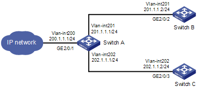
As shown in Figure 3-1, redirect all packets received on GigabitEthernet 2/0/1 of Switch A to the next hop 202.1.1.2.
Figure 3-1 Network diagram for IPv4 policy-based routing configuration
l Configuration procedure
# Configure ACL 2000.
<SwitchA> system-view
[SwitchA] acl number 2000
[SwitchA-acl-basic-2000] rule 0 permit source any
[SwitchA-acl-basic-2000] quit
# Define a match criterion for class a to match ACL 2000.
[SwitchA] traffic classifier a
[SwitchA-classifier-a] if-match acl 2000
[SwitchA-classifier-a] quit
# Configure the action of redirecting traffic to the next hop 202.1.1.2 for behavior a.
[SwitchA] traffic behavior a
[SwitchA-behavior-a] redirect next-hop 202.1.1.2
[SwitchA-behavior-a] quit
# Associate class a with behavior a in QoS policy a.
[SwitchA] qos policy a
[SwitchA-qospolicy-a] classifier a behavior a
[SwitchA-qospolicy-a] quit
# Apply QoS policy a to the inbound direction of GigabitEthernet 2/0/1.
[SwitchA] interface gigabitethernet 2/0/1
[SwitchA-GigabitEthernet2/0/1] qos apply policy a inbound
l Verification
After the configuration is finished, verify that when Switch A receives packets with destination IP address 201.1.1.2, it forwards the packets to Switch C instead of Switch B.
IPv6 Policy-Based Routing Configuration Example
l Network requirements
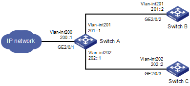
As shown in Figure 3-2, redirect all packets received on GigabitEthernet 2/0/1 of Switch A to the next hop 202::2.
Figure 3-2 Network diagram for IPv6 policy-based routing configuration
l Configuration procedure
# Configure IPv6 ACL 2000.
<SwitchA> system-view
[SwitchA] acl ipv6 number 2000
[SwitchA-acl6-basic-2000] rule 0 permit source any
[SwitchA-acl6-basic-2000] quit
# Define a match criterion for class a to match IPv6 ACL 2000.
[SwitchA] traffic classifier a
[SwitchA-classifier-a] if-match acl ipv6 2000
[SwitchA-classifier-a] quit
# Configure the action of redirecting traffic to the next hop 202::2 for behavior a.
[SwitchA] traffic behavior a
[SwitchA-behavior-a] redirect next-hop 202::2
[SwitchA-behavior-a] quit
# Associate class a with behavior a in QoS policy a.
[SwitchA] qos policy a
[SwitchA-qospolicy-a] classifier a behavior a
[SwitchA-qospolicy-a] quit
# Apply QoS policy a to the inbound direction of GigabitEthernet 2/0/1.
[SwitchA] interface gigabitethernet 2/0/1
[SwitchA-GigabitEthernet2/0/1] qos apply policy a inbound
l Verification
After the configuration is finished, verify that when Switch A receives packets with destination IP address 201::2, it forwards the packets to Switch C instead of Switch B.
Displaying and Maintaining QoS Policies
|
To do… |
Use the command… |
Remarks |
|
Display information about a class and the corresponding actions associated by a policy |
display qos policy user-defined [ policy-name [ classifier classifier-name ] ] |
Available in any view |
|
Display information about the policies applied on a port |
display qos policy interface [ interface-type interface-number ] [ inbound | outbound ] |
Available in any view |
|
Display information about a traffic behavior |
display traffic behavior user-defined [ behavior-name ] |
Available in any view |
|
Display information about a class |
display traffic classifier user-defined [ classifier-name ] |
Available in any view |
|
Display information about a global QoS policy |
display qos policy global { inbound | outbound } [ slot slot-id ] |
Available in any view |
|
Display information about QoS policies applied to VLANs |
display qos vlan-policy { name policy-name | vlan [ vlan-id ] } [ slot slot-id ] |
Available in any view |
|
Clear the statistics of a global QoS policy |
reset qos policy global { inbound | outbound } |
Available in user view |
|
Clear the statistics of QoS policies applied to VLANs |
reset qos vlan-policy [ vlan vlan-id ] |
Available in user view |
When configuring congestion management, go to these section for information that you are interested in:
l Overview
l Congestion Management Policy
l Displaying and Maintaining Congestion Management
Overview
When the rate at which the packets arrive is higher than the rate at which the packets are transmitted on an interface, congestion occurs on this interface. If there is not enough storage space to store these packets, parts of them will be lost. Packet loss may cause the transmitting device to retransmit the packets because the lost packets time out, which causes a malicious cycle.
The core of congestion management is how to schedule the resources and determine the sequence of forwarding packets when congestion occurs.
Congestion Management Policy
Queuing technology is generally adopted to solve the congestion problem. The queuing technology is to classify the traffic according to a specified queue-scheduling algorithm and then use the specified priority algorithm to forward the traffic. Each queuing algorithm is used to solve specific network traffic problems and affects the parameters such as bandwidth allocation, delay and delay jitter.
1) SP queue-scheduling algorithm
Figure 4-1 Diagram for SP queuing
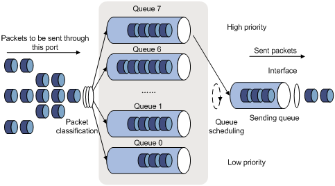
SP queue-scheduling algorithm is specially designed for critical service applications. An important feature of critical services is that they demand preferential service in congestion in order to reduce the response delay. Assume that there are eight output queues on the port and the preferential queue classifies the eight output queues on the port into eight classes, which are queue7, queue6, queue5, queue4, queue3, queue2, queue1, and queue0. Their priorities decrease in order.
In queue scheduling, SP sends packets in the queue with higher priority strictly following the priority order from high to low. When the queue with higher priority is empty, packets in the queue with lower priority are sent. You can put critical service packets into the queues with higher priority and put non-critical service (such as e-mail) packets into the queues with lower priority. In this case, critical service packets are sent preferentially and non-critical service packets are sent when critical service groups are not sent.
The disadvantage of SP queue is that: if there are packets in the queues with higher priority for a long time in congestion, the packets in the queues with lower priority will be “starved” because they are not served.
2) WRR queue-scheduling algorithm
Figure 4-2 Diagram for WRR queuing
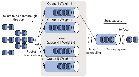
A port of the switch supports eight outbound queues. The WRR queue-scheduling algorithm schedules all the queues in turn to ensure that every queue can be assigned a certain service time. Assume there are eight output queues on the port. The eight weight values (namely, w 7, w 6, w 5, w 4, w 3, w 2, w 1, and w 0) indicating the proportion of assigned resources are assigned to the eight queues respectively. On a 100M port, you can configure the weight values of WRR queue-scheduling algorithm to 50, 30, 10, 10, 50, 30, 10, and 10 (corresponding to w7, w6, w5, w4, w3, w2, w1, and w0 respectively). In this way, the queue with the lowest priority can be assured of 5 Mbps of bandwidth at least, thus avoiding the disadvantage of SP queue-scheduling algorithm that packets in low-priority queues are possibly not to be served for a long time. Another advantage of WRR queue-scheduling algorithm is that though the queues are scheduled in turn, the service time for each queue is not fixed, that is to say, if a queue is empty, the next queue will be scheduled immediately. In this way, the bandwidth resources are fully utilized.
3) WFQ queue-scheduling algorithm
Figure 4-3 Diagram for WFQ queuing
Before WFQ is introduced, you need to understand fair queuing (FQ). FQ is designed for fairly sharing network resources, reducing the delay and jitter of all traffic. FQ takes all the aspects into consideration:
l Different queues have fair dispatching opportunities for delay balancing among streams.
l Short packets and long packets are fairly scheduled: if there are long packets and short packets in queues, statistically the short packets should be scheduled preferentially to reduce the jitter between packets on the whole.
Compared with FQ, WFQ takes weights into account when determining the queue scheduling order. Statistically, WFQ gives high priority traffic more scheduling opportunities than low priority traffic. WFQ can automatically classify traffic according to the “session” information of traffic (protocol type, TCP or UDP source/destination port numbers, source/destination IP addresses, IP precedence bits in the ToS field, etc), and try to provide as many queues as possible so that each traffic flow can be put into these queues to balance the delay of every traffic flow on a whole. When dequeuing packets, WFQ assigns the outgoing interface bandwidth to each traffic flow by the precedence. The higher precedence value a traffic flow has, the more bandwidth it gets.
The S7500E series switches introduce the minimum guaranteed bandwidth mechanism, and use it in conjunction with WFQ as follows:
l The minimum guaranteed bandwidth configuration guarantees a certain amount of bandwidth for each WFQ queue.
l The allocable bandwidth (allocable bandwidth = the total bandwidth – the sum of the minimum guaranteed bandwidth for each queue) is divided and allocated to each queue based on queue precedence.
For example, assume that the total bandwidth of an interface is 10 Mbps and there are five flows on the interface, with the precedence being 0, 1, 2, 3, and 4 respectively and the minimum guaranteed bandwidth being 128 kbps, 128 kbps, 128 kbps, 64 kbps, and 64 kbps respectively. Then,
l The allocable bandwidth = 10 Mbps – (128 + 128 + 128 + 64 + 64) kbps = 9.5 Mbps
l The total allocable bandwidth quota is the sum of all the (precedence value + 1)s, that is, 1 + 2 + 3 + 4 + 5 = 15.
l The bandwidth percentage assigned to each flow is (precedence value of the flow + 1)/total allocable bandwidth quota. The bandwidth percentages for flows are 1/15, 2/15, 3/15, 4/15, and 5/15 respectively.
l The bandwidth allocated to a queue = Minimum guaranteed bandwidth + bandwidth allocated to the queue from the allocable bandwidth
Because WFQ can balance the delay and jitter of every flow when congestion occurs, it is effectively applied in some special occasions. For example, WFQ is adopted in the assured forwarding (AF) services of the Resource Reservation Protocol (RSVP). In Generic Traffic Shaping (GTS), WFQ is used to schedule buffered packets.
The S7500E series generally support the following four queue scheduling algorithms:
l All the queues are scheduled with the SP algorithm.
l All the queues are scheduled with the WRR algorithm.
l All the queues are scheduled with the WFQ algorithm
l Some queues are scheduled with the SP algorithm, while other queues are scheduled with the WRR algorithm.
Configuring an SP Queue
Configuration Procedure
Follow these steps to configure SP queues:
|
To do… |
Use the command… |
Remarks |
|
|
Enter system view |
system-view |
— |
|
|
Enter port view or port group view |
Enter port view |
interface interface-type interface-number |
Perform either of the two operations. The configuration performed in Ethernet interface view applies to the current port only. The configuration performed in port group view applies to all the ports in the port group. |
|
Enter port group view |
port-group manual port-group-name |
||
|
Configure SP queue scheduling algorithm |
qos sp |
Optional By default, SP queue scheduling algorithm is adopted on all the ports. |
|
Configuration Example
Network requirements
Configure GigabitEthernet2/0/1 to adopt SP queue scheduling algorithm.
Configuration procedure
# Enter system view.
<Sysname> system-view
# Configure an SP queue for GigabitEthernet2/0/1 port.
[Sysname] interface GigabitEthernet 2/0/1
[Sysname-GigabitEthernet2/0/1] qos sp
Configuring a WRR Queue
By default, SP queue scheduling algorithm is adopted on all the ports. You can adopt WRR queue scheduling algorithm as required.
Configuration Procedure
Follow these steps to configure WRR queues:
|
To do… |
Use the command… |
Remarks |
|
|
Enter system view |
system-view |
— |
|
|
Enter port view or port group view |
Enter port view |
interface interface-type interface-number |
Perform either of the two operations. The configuration performed in Ethernet interface view applies to the current port only. The configuration performed in port group view applies to all the ports in the port group |
|
Enter port group view |
port-group manual port-group-name |
||
|
Adopt the WRR queue scheduling on the port |
qos wrr |
Required By default, SP queue scheduling algorithm is adopted on all the ports. |
|
|
Configure WRR queue scheduling |
qos wrr queue-id group group-id weight schedule-value |
Required |
|
Configuration Example
Network requirements
Configure WRR queue scheduling algorithm on GigabitEthernet 2/0/1, and assign weight 1, 2, 4, 6, 8, 10, 12, and 14 to queue 0 through queue 7.
Configuration procedure
# Enter system view.
<Sysname> system-view
# Configure the WRR queues on GigabitEthernet2/0/1 port.
[Sysname] interface GigabitEthernet 2/0/1
[Sysname-GigabitEthernet2/0/1] qos wrr
[Sysname-GigabitEthernet2/0/1] qos wrr 0 group 1 weight 1
[Sysname-GigabitEthernet2/0/1] qos wrr 1 group 1 weight 2
[Sysname-GigabitEthernet2/0/1] qos wrr 2 group 1 weight 4
[Sysname-GigabitEthernet2/0/1] qos wrr 3 group 1 weight 6
[Sysname-GigabitEthernet2/0/1] qos wrr 4 group 1 weight 8
[Sysname-GigabitEthernet2/0/1] qos wrr 5 group 1 weight 10
[Sysname-GigabitEthernet2/0/1] qos wrr 6 group 1 weight 12
[Sysname-GigabitEthernet2/0/1] qos wrr 7 group 1 weight 14
Configuring a WFQ Queue
By default, all ports adopt the SP queue algorithm. You can configure a port to use the WFQ algorithm instead on an LPU as required.
Configuration Procedure
Follow these steps to configure WFQ queues:
|
To do… |
Use the command… |
Remarks |
|
|
Enter system view |
system-view |
— |
|
|
Enter port view or port group view |
Enter port view |
interface interface-type interface-number |
Perform either of the two operations. The configuration performed in Ethernet interface view applies to the current port only. The configuration performed in port group view applies to all the ports in the port group |
|
Enter port group view |
port-group manual port-group-name |
||
|
Adopt the WFQ queue scheduling on the port |
qos wfq |
Required By default, SP queue scheduling algorithm is adopted on all the ports. |
|
|
Configure the minimum guaranteed bandwidth for a WFQ queue |
qos bandwidth queue queue-id min bandwidth-value |
Optional |
|
|
Configure a scheduling weight for the specified queue |
qos wfq queue-id weight schedule-value |
Optional By default, the scheduling weight of a WFQ queue is 1. |
|
Configuration Example
Network requirements
Enable WFQ on GigabitEthernet 2/0/1 on a non-EA LPU and assign weight values 1, 2, 4, 6, 8, 10, 12, and 14 to queues 0 through 7 respectively.
Configuration procedure
# Enter system view.
<Sysname> system-view
# Configure the WFQ queues on GigabitEthernet2/0/1 port.
[Sysname] interface GigabitEthernet 2/0/1
[Sysname-GigabitEthernet2/0/1] qos wfq
[Sysname-GigabitEthernet2/0/1] qos wfq 0 weight 1
[Sysname-GigabitEthernet2/0/1] qos wfq 1 weight 2
[Sysname-GigabitEthernet2/0/1] qos wfq 2 weight 4
[Sysname-GigabitEthernet2/0/1] qos wfq 3 weight 6
[Sysname-GigabitEthernet2/0/1] qos wfq 4 weight 8
[Sysname-GigabitEthernet2/0/1] qos wfq 5 weight 10
[Sysname-GigabitEthernet2/0/1] qos wfq 6 weight 12
[Sysname-GigabitEthernet2/0/1] qos wfq 7 weight 14
Configuring SP+WRR Queues
As required, you can configure part of the queues on the port to adopt the SP queue-scheduling algorithm and parts of queues to adopt the WRR queue-scheduling algorithm. Through adding the queues on a port to the SP scheduling group and WRR scheduling group (namely, group 1), the SP+WRR queue scheduling is implemented. During the queue scheduling process, the queues in the SP scheduling group is scheduled preferentially. When no packet is to be sent in the queues in the SP scheduling group, the queues in the WRR scheduling group are scheduled. The queues in the SP scheduling group are scheduled according to the strict priority of each queue, while the queues in the WRR queue scheduling group are scheduled according the weight value of each queue.
Configuration Procedure
Follow these steps to configure SP + WRR queues:
|
To do… |
Use the command… |
Remarks |
|
|
Enter system view |
system-view |
— |
|
|
Enter port view or port group view |
Enter port view |
interface interface-type interface-number |
Perform either of the two operations. The configuration performed in Ethernet interface view applies to the current port only. The configuration performed in port group view applies to all the ports in the port group. |
|
Enter port group view |
port-group manual port-group-name |
||
|
Enable the WRR queue scheduling on the port |
qos wrr |
Required By default, SP queue scheduling algorithm is adopted on all the ports. |
|
|
Configure SP queue scheduling |
qos wrr queue-id group sp |
Required |
|
|
Configure WRR queue scheduling |
qos wrr queue-id group group-id weight schedule-value |
Required |
|
Configuration Example
Network requirements
l Configure to adopt SP+WRR queue scheduling algorithm on GigabitEthernet2/0/1.
l Configure queue 0, queue 1, queue 2 and queue 3 on GigabitEthernet2/0/1 to be in SP queue scheduling group.
l Configure queue 4, queue 5, queue 6 and queue 7 on GigabitEthernet2/0/1 to be in WRR queue scheduling group, with the weight being 2, 4, 6 and 8 respectively.
Configuration procedure
# Enter system view.
<Sysname> system-view
# Enable the SP+WRR queue scheduling algorithm on GigabitEthernet2/0/1.
[Sysname] interface GigabitEthernet 2/0/1
[Sysname-GigabitEthernet2/0/1] qos wrr
[Sysname-GigabitEthernet2/0/1] qos wrr 0 group sp
[Sysname-GigabitEthernet2/0/1] qos wrr 1 group sp
[Sysname-GigabitEthernet2/0/1] qos wrr 2 group sp
[Sysname-GigabitEthernet2/0/1] qos wrr 3 group sp
[Sysname-GigabitEthernet2/0/1] qos wrr 4 group 1 weight 2
[Sysname-GigabitEthernet2/0/1] qos wrr 5 group 1 weight 4
[Sysname-GigabitEthernet2/0/1] qos wrr 6 group 1 weight 6
[Sysname-GigabitEthernet2/0/1] qos wrr 7 group 1 weight 8
Displaying and Maintaining Congestion Management
|
To do… |
Use the command… |
Remarks |
|
Display WRR queue configuration information |
display qos wrr interface [ interface-type interface-number ] |
Available in any view |
|
Display SP queue configuration information |
display qos sp interface [ interface-type interface-number ] |
|
|
Display WFQ queue configuration information |
display qos wfq interface [ interface-type interface-number ] |
When configuring congestion avoidance, go to these sections for information you are interested in:
l Congestion Avoidance Overview
l Displaying and Maintaining WRED
Congestion Avoidance Overview
Serious congestion causes great damages to the network resources, and therefore some measures must be taken to avoid such congestion. As a flow control mechanism, congestion avoidance can actively drop packets when congestion deteriorates through monitoring the utilization of network resources (such as queues or memory buffers) to prevent network overload.
Compared to point-to-point flow control, this flow control mechanism is of broader sense because it can control the load of more flows in a device. When dropping packets from a source end, it can still cooperate well with the flow control mechanism (such as TCP flow control) at the source end to better adjust the network traffic to a reasonable load status. The combination of the packet drop policy of the local device and the flow control mechanism at the source end can maximize throughput and utilization rate of the network and minimize packet loss and delay.
Traditional packet drop policy
The traditional packet drop policy is tail drop. When the length of a queue reaches the maximum threshold, all the subsequent packets are dropped.
Such a policy results in global TCP synchronization. That is, if packets from multiple TCP connections are dropped, these TCP connections go into the state of congestion avoidance and slow start to reduce traffic, but traffic peak occurs later. Consequently, the network traffic jitters all the time.
RED and WRED
You can use random early detection (RED) or weighted random early detection (WRED) to avoid global TCP synchronization.
The RED or WRED algorithm sets an upper threshold and lower threshold for each queue, and processes the packets in a queue as follows:
l When the queue size is shorter than the lower threshold, no packet is dropped;
l When the queue size reaches the upper threshold, all subsequent packets are dropped;
l When the queue size is between the lower threshold and the upper threshold, the received packets are dropped at random. The longer a queue is, the higher the drop probability is. However, a maximum drop probability exists.
Different from RED, WRED determines differentiated drop policies for packets with different IP precedence values. Packets with a lower IP precedence are more likely to be dropped.
Both RED and WRED avoid global TCP synchronization by randomly dropping packets. When the sending rate of a TCP session slows down after its packets are dropped, the other TCP sessions remain in high packet sending rates. In this way, some TCP sessions remain in high sending rates in any case, and the link bandwidth can be fully utilized.
Configuring WRED
![]()
Only EA and SC LPUs support WRED.
Configuration Prerequisites
Before configuring WRED, determine the following:
l The parameters to be configured in the WRED table
l The port/port group where the WRED table is to be applied
Configuration Procedure
Follow these steps to configure WRED:
|
To do… |
Use the command… |
Remarks |
|
|
Enter system view |
system-view |
— |
|
|
Create a WRED table |
qos wred queue table table-name |
— |
|
|
Configure drop parameters for the WRED table |
queue queue-id [ drop-level drop-level ] low-limit low-limit [ discard-probability discard-prob ] |
Optional By default, the low-limit argument is 10 and the discard-prob argument is 10. |
|
|
Enter port view or port group view |
Enter port view |
interface interface-type interface-number |
Use either command The configuration performed in Ethernet interface view applies to the current port only. The configuration performed in port group view applies to all the ports in the port group. |
|
Enter port group view |
port-group manual port-group-name |
||
|
Apply the WRED table |
qos wred apply table-name |
Required |
|
Configuration Example
Network requirements
Create a WRED table with the default parameters and apply the WRED table to GigabitEthernet 2/0/1.
Configuration procedure
# Enter system view.
<Sysname> system-view
# Create a WRED table with the default parameters.
[Sysname] qos wred queue table queue-table1
[Sysname-wred-table-queue-table1] quit
# Apply the WRED table to GigabitEthernet 2/0/1.
[Sysname] interface GigabitEthernet 2/0/1
[Sysname-GigabitEthernet2/0/1] qos wred apply queue-table1
Displaying and Maintaining WRED
|
To do… |
Use the command… |
Remarks |
|
Display the WRED configuration of a port |
display qos wred interface [ interface-type interface-number ] |
Available in any view |
|
Display the configuration of a WRED table |
display qos wred table [ table-name ] |
Available in any view |
When configuring priority mapping, go to these sections for information you are interested in:
l Priority
l Configuring a Priority Mapping Table
l Configuring the Port Priority
l Configuring Port Priority Trust Mode
l Displaying and Maintaining Priority Mapping
Priority
The following describes several types of precedence:
1) IP precedence, ToS precedence, and DSCP precedence
Figure 6-1 DS field and ToS field
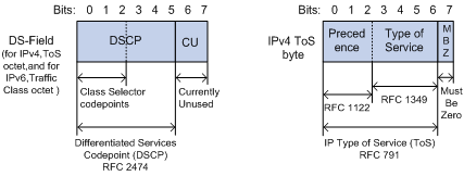
The ToS field in an IP header contains eight bits, which are described as follows:
l The first three bits indicate IP precedence in the range of 0 to 7.
l Bit 3 to bit 6 indicate ToS precedence in the range of 0 to 15.
l RFC2474 re-defines the ToS field in the IP packet header, which is called the DS field. The first six (bit 0 to bit 5) bits of the DS field indicate DSCP precedence in the range of 0 to 63. The last two bits (bit 6 and bit 7) are reserved bits.
Table 6-1 Description on IP Precedence
|
IP Precedence (decimal) |
IP Precedence (binary) |
Description |
|
0 |
000 |
Routine |
|
1 |
001 |
priority |
|
2 |
010 |
immediate |
|
3 |
011 |
flash |
|
4 |
100 |
flash-override |
|
5 |
101 |
critical |
|
6 |
110 |
internet |
|
7 |
111 |
network |
In a network providing differentiated services, traffics are grouped into the following four classes, and packets are processed according to their DSCP values.
l Expedited Forwarding (EF) class: In this class, packets can be forwarded regardless of link share of other traffic. The class is suitable for preferential services with low delay, low packet loss ratio, low jitter, and assured bandwidth (such as virtual leased line);
l Assured forwarding (AF) class: This class is further divided into four subclasses (AF1/2/3/4) and a subclass is further divided into three drop priorities, so the AF service level can be segmented. The QoS rank of the AF class is lower than that of the EF class;
l Class selector (CS) class: This class comes from the IP ToS field and includes eight subclasses;
l Best Effort (BE) class: This class is a special class without any assurance in the CS class. The AF class can be degraded to the BE class if it exceeds the limit. Current IP network traffic belongs to this class by default.
Table 6-2 Description on DSCP precedence values
|
DSCP value (decimal) |
DSCP value (binary) |
Description |
|
46 |
101110 |
ef |
|
10 |
001010 |
af11 |
|
12 |
001100 |
af12 |
|
14 |
001110 |
af13 |
|
18 |
010010 |
af21 |
|
20 |
010100 |
af22 |
|
22 |
010110 |
af23 |
|
26 |
011010 |
af31 |
|
28 |
011100 |
af32 |
|
30 |
011110 |
af33 |
|
34 |
100010 |
af41 |
|
36 |
100100 |
af42 |
|
38 |
100110 |
af43 |
|
8 |
001000 |
cs1 |
|
16 |
010000 |
cs2 |
|
24 |
011000 |
cs3 |
|
32 |
100000 |
cs4 |
|
40 |
101000 |
cs5 |
|
48 |
110000 |
cs6 |
|
56 |
111000 |
cs7 |
|
0 |
000000 |
be (default) |
2) 802.1p priority
802.1p priority lies in Layer 2 packet headers and is applicable to occasions where the Layer 3 packet header does not need analysis but QoS must be assured at Layer 2.
Figure 6-2 An Ethernet frame with an 802.1Q tag header
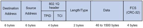
As shown in the figure above, the 4-byte 802.1Q tag header contains a 2-byte Tag Protocol Identifier (TPID) whose value is 8100 and a 2-byte Tag Control Information (TCI). TPID is a new class defined by IEEE to indicate a packet with an 802.1Q tag. Figure 6-3 describes the detailed contents of an 802.1Q tag header.
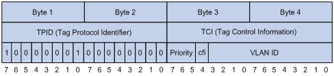
In the figure above, the 3-bit priority field in TCI is 802.1p priority in the range of 0 to 7. In the figure above, the priority field (three bits in length) in TCI is 802.1p priority (also known as CoS precedence), which ranges from 0 to 7.
Table 6-3 Description on 802.1p priority
|
802.1p priority (decimal) |
802.1p priority (binary) |
Description |
|
0 |
000 |
best-effort |
|
1 |
001 |
background |
|
2 |
010 |
spare |
|
3 |
011 |
excellent-effort |
|
4 |
100 |
controlled-load |
|
5 |
101 |
video |
|
6 |
110 |
voice |
|
7 |
111 |
network-management |
The precedence is called 802.1p priority because the related applications of this precedence are defined in detail in the 802.1p specifications.
Priority Mapping Overview
The local precedence and drop precedence are described as follows.
l Local precedence is the precedence that the switch assigns to a packet and it is corresponding to the number of an outbound queue on the port. Local precedence takes effect only on the local switch.
l Drop precedence is a parameter that is referred to when dropping packets. The higher the drop precedence, the more likely a packet is dropped.
Depending on whether a received packet is 802.1q-tagged, the switch marks it with priority as follows:
1) For an 802.1q-untagged packet
When a packet carrying no 802.1q tag reaches a port, the switch uses the port priority as the 802.1p precedence value of the received packet, searches for the local precedence value corresponding to the port priority of the receiving port in the 802.1p-precedence-to-local-precedence mapping table, assigns the local precedence value to the packet, and enqueues the packet according to the local precedence value.
2) For an 802.1q-tagged packet
When an 802.1q tagged packet reaches the port of a switch, you can specify a priority trust mode for the port as follows.
S7500E series Ethernet switches provide the following two priority trust modes:
l Trusting the DSCP precedence of received packets. In this mode, the switch searches the dscp-dot1p/dp/dscp mapping table based on the DSCP precedence of the received packet for the 802.1p precedence/drop precedence/DSCP precedence to be used to mark the packet. Then the switch searches the dot1p-lp mapping table based on the marked 802.1p precedence for the corresponding local precedence and marks the received packet with the local precedence.
l Trusting the 802.1p precedence of received packets. In this mode, if a packet is received without an 802.1q tag, the switch takes the priority of the receiving port as the 802.1p precedence of the packet and then based on the priority searches the dot1p-dp/lp mapping table for the local/drop precedence for the packet. If packet is received with an 802.1q tag, the switch searches the dot1p-dp/lp mapping table based on the 802.1p precedence in the tag for local/drop precedence for the packet.
The default dot1p-lp/dp mapping and dscp-dot1p/dp/dscp mapping provided by S7500E series Ethernet switches are shown in the following two tables.
Table 6-4 The default values of dot1p-lp mapping and dot1p-dp mapping
|
Imported priority value |
dot1p-lp mapping |
dot1p-dp mapping |
|
802.1p precedence (dot1p) |
Local precedence (lp) |
Drop precedence (dp) |
|
0 |
2 |
0 |
|
1 |
0 |
0 |
|
2 |
1 |
0 |
|
3 |
3 |
0 |
|
4 |
4 |
0 |
|
5 |
5 |
0 |
|
6 |
6 |
0 |
|
7 |
7 |
0 |
Table 6-5 The default values of dscp-dp mapping, dscp-dot1p mapping, and dscp-dscp mapping
|
Imported priority value |
dscp-dp mapping |
dscp-dot1p mapping |
|
DSCP precedence (dscp) |
Drop precedence (dp) |
802.1p precedence (dot1p) |
|
0 to 7 |
0 |
0 |
|
8 to 15 |
0 |
1 |
|
16 to 23 |
0 |
2 |
|
24 to 31 |
0 |
3 |
|
32 to 39 |
0 |
4 |
|
40 to 47 |
0 |
5 |
|
48 to 55 |
0 |
6 |
|
56 to 63 |
0 |
7 |
![]()
For the default dscp-dscp mappings, an input value yields a target value that is equal to it.
Configuring a Priority Mapping Table
You can modify the priority mapping tables in a switch as required.
Follow the two steps to configure priority mapping tables:
l Enter priority mapping table view;
l Configure priority mapping parameters.
Configuration Prerequisites
The new priority mapping table is determined.
Configuration Procedure
Follow these steps to configure a priority mapping table:
|
To do… |
Use the command… |
Remarks |
|
Enter system view |
system-view |
— |
|
Enter priority mapping table view |
qos map-table { dot1p-dp | dot1p-lp | dscp-dot1p | dscp-dp | dscp-dscp } |
Required To configure a priority mapping table, you need to enter the corresponding priority mapping table view. |
|
Configure priority mapping parameters |
import import-value-list export export-value |
Required The newly configured mapping entries overwrite the corresponding previous entries. |
![]()
You cannot configure to map any DSCP value to drop precedence 1.
Configuration Example
Network requirements
Modify the dot1p-lp mapping table as those listed in Table 6-6.
Table 6-6 The specified dot1p-lp mapping
|
802.1p precedence |
Local precedence |
|
0 |
0 |
|
1 |
0 |
|
2 |
1 |
|
3 |
1 |
|
4 |
2 |
|
5 |
2 |
|
6 |
3 |
|
7 |
3 |
Configuration procedure
# Enter system view.
<Sysname> system-view
# Enter dot1p-lp priority mapping table view.
[Sysname] qos map-table dot1p-lp
# Modify dot1p-lp priority mapping parameters.
[Sysname-maptbl-dot1p-lp] import 0 1 export 0
[Sysname-maptbl-dot1p-lp] import 2 3 export 1
[Sysname-maptbl-dot1p-lp] import 4 5 export 2
[Sysname-maptbl-dot1p-lp] import 6 7 export 3
Configuring the Port Priority
By default, if a port receives packets without 802.1q tags, the switch takes the priority of the receiving port as the 802.1p precedence of the received packets, searches the dot1p-lp/dp mapping table for the corresponding local precedence and drop precedence according to the 802.1p precedence of the received packets, and then marks the received packets with the corresponding local precedence and drop precedence.
Port priority is in the range 0 to 7. You can set the port priority as required.
Configuration Prerequisites
The port priority of the port is determined.
Configuration Procedure
Follow these steps to configure port priority:
|
To do… |
Use the command… |
Remarks |
|
|
Enter system view |
system-view |
— |
|
|
Enter port view or port group view |
Enter port view |
interface interface-type interface-number |
Perform either of the two operations. The configuration performed in Ethernet interface view applies to the current port only. The configuration performed in port group view applies to all the ports in the port group. |
|
Enter port group view |
port-group manual port-group-name |
||
|
Configure port priority |
qos priority priority-value |
Required By default, the port priority is 0. |
|
Configuration Example
Network requirements
Configure the port priority to 7.
Configuration procedure
# Enter system view.
<Sysname> system-view
# Configure port priority of GigabitEthernet2/0/1.
[Sysname] interface GigabitEthernet 2/0/1
[Sysname-GigabitEthernet2/0/1] qos priority 7
Configuring Port Priority Trust Mode
You can configure the switch to trust the DSCP precedence of the received packets. In this case, the switch searches the dscp-dot1p/dp/dscp mapping table for the corresponding precedence according to the DSCP precedence of the packets and marks the received packets with the precedence.
Configuration Prerequisites
It is determined to trust the DSCP precedence of received packets.
Configuration Procedure
Follow these steps to configure the port priority trust mode:
|
To do… |
Use the command… |
Remarks |
|
|
Enter system view |
system-view |
— |
|
|
Enter port view or port group view |
Enter port view |
interface interface-type interface-number |
Perform either of the two operations. The configuration performed in Ethernet interface view applies to the current port only. The configuration performed in port group view applies to all the ports in the port group. |
|
Enter port group view |
port-group manual port-group-name |
||
|
Configure to trust the DSCP precedence of the received packets |
qos trust dscp |
Required By default, the 802.1p precedence of the received packets is trusted. |
|
Configuration Example
Network requirements
Configure to trust the DSCP precedence of the received packets.
Configuration procedure
# Enter system view.
<Sysname> system-view
# Enter port view.
[Sysname] interface GigabitEthernet 2/0/1
[Sysname-GigabitEthernet2/0/1]
# Configure to trust the DSCP precedence of the received packets.
[Sysname-GigabitEthernet2/0/1] qos trust dscp
Displaying and Maintaining Priority Mapping
|
To do… |
Use the command… |
Remarks |
|
Display the information about a specified priority mapping table |
display qos map-table [ dot1p-dp | dot1p-lp | dscp-dot1p | dscp-dp | dscp-dscp ] |
Available in any view |
|
Display the priority trust mode configured for a port |
display qos trust interface [ interface-type interface-number ] |
When configuring QoS in an EPON system, go to these sections for information you are interested in:
l Configuring QoS in an EPON System
QoS in an EPON System
An S7500E switch installed with an OLT card can work as an OLT in an EPON system. For detailed information about an EPON system, refer to the Introduction to EPON System part in EPON-OLT Configuration.
You can configure QoS for an OLT and ONUs attached to the OLT. To achieve QoS in an EPON system, you must configure QoS at both the OLT side and the ONU side. The following part introduces QoS functions that can be configured for uplink traffic and those for the downlink traffic.
QoS Functions for Uplink Traffic
Processing on an ONU
l Configuring the priority trust mode for an ONU.
l Configuring traffic classification for an ONU: the ONU classifies the uplink traffic of a UNI and marks CoS precedence values for the matching traffic, so that traffic can be put into different queues.
l Filtering the packets matching certain match criteria according to the configured QoS policy.
l Configuring the ONU to perform traffic policing for uplink traffic of a UNI.
l Configuring the UNI to tag the uplink 802.1q-untagged traffic with the default VLAN tag, and adding the UNI priority to the Priority field as the 802.1p precedence (CoS precedence).
l Configuring the ONU to distribute the uplink traffic to different output queues based on the mapping between the CoS precedence and local precedence.
l Configuring the ONU to perform congestion management for traffic from uplink ports, supporting SP and WFQ queue scheduling algorithms (available to only H3C ONUs).
Processing on an OLT
l By default, an OLT port trusts the 802.1p precedence of the packets. You can configure to trust the DSCP precedence of the packets through the command line. Thus, the OLT will obtain the CoS precedence based on the mapping between the DSCP precedence and CoS precedence before mapping the CoS precedence to the corresponding output queue. This configuration applies to all uplink traffic of ONUs.
l Configuring congestion management for uplink ports (supporting SP, WRR, and SP+WRR queue scheduling algorithms).
l Configuring congestion avoidance on an OLT. When the port is congested, received packets are dropped selectively.
Figure 7-1 shows the QoS model for uplink traffic in an EPON system.
Figure 7-1 QoS model for uplink traffic in an EPON system
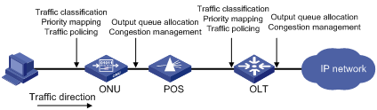
QoS Functions for Downlink Traffic
Processing on an OLT
l Configuring the OLT to perform priority mapping for packets received from the uplink port according to the CoS-to-local precedence mapping table and then assign packets to output queues of the OLT port.
l Configuring the OLT to perform congestion management for downlink traffic, supporting SP and WRR queue scheduling algorithms.
l Configuring the OLT to perform line rate and traffic shaping for downlink traffic.
l Configuring the maximum downlink bandwidth that the OLT assigns to the ONU.
l Configuring high-priority packet buffer for downlink traffic that the OLT sends to the specified ONU.
Processing on an ONU
l Filtering the packets matching certain match criteria according to the configured QoS policy.
l Configuring the ONU to distribute the received downlink traffic to different output queues based on the mapping between the CoS precedence and local precedence.
l Configuring the ONU to perform traffic policing for downlink traffic of a UNI.
![]()
Some ONUs support configuring queue scheduling for traffic from a UNI. To perform such configurations, you should log in to the ONU. For detailed configuration, refer to the ONU user manual.
Figure 7-2 shows the QoS model for downlink traffic in an EPON system.
Figure 7-2 QoS model for downlink traffic in an EPON system
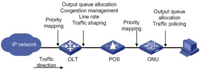
Configuring QoS in an EPON System
QoS Configuration Task List in an EPON System
![]()
QoS configurations in an EPON system are the same as those in Ethernet, and the corresponding configuration commands in OLT port view and ONU port view are the same as those in Ethernet port view too. For detailed configuration, refer to the corresponding chapters above.
Table 7-1 and Table 7-2 show how to configure QoS for downlink traffic and uplink traffic in an EPON system.
Table 7-1 Configure QOS at the OLT side of an EPON system
|
QoS at the OLT side |
Reference |
|
|
Configure QoS for uplink traffic |
Configure priority mapping on the OLT |
|
|
Configuring priority trust mode for the OLT port |
||
|
Configure traffic policing for uplink traffic of all ONUs (through QoS) |
||
|
Configure congestion management on the uplink port |
||
|
Configure QoS for downlink traffic |
Configure the OLT to perform priority mapping for traffic received on an uplink port |
|
|
Configure congestion management (SP and WRR) on the downlink OLT port |
||
|
Configure the high-priority queue buffer for the specified ONU |
||
|
Configure line rate and traffic shaping for downlink traffic |
||
|
Assign downlink bandwidth for each ONU |
||
Table 7-2 Configure QoS at the ONU side of an EPON system
|
QoS at the ONU side |
Reference |
|
|
Configure QoS for uplink traffic |
Configuring traffic classification and CoS priority marking for incoming packets on UNIs |
|
|
Configure priority trust mode for the ONU |
||
|
Configuring traffic policing for uplink traffic of a UNI |
Configure traffic policing for downlink/uplink traffic of a UNI |
|
|
Configure congestion management for the uplink port of an ONU |
||
|
Configure QoS for downlink traffic |
Configure the ONU to perform priority mapping for downlink traffic from the OLT according to the CoS-to-local precedence mapping table |
|
|
Set the ONU port priority |
||
|
Configuring traffic policing for downlink traffic of a UNI |
Configure traffic policing for downlink/uplink traffic of a UNI |
|
Configuring QoS at the OLT side
Modify the priority mapping on the OLT port
Follow these steps to modify the 802.1p-to-local mapping on the OLT port:
|
To do… |
Use the command… |
Remarks |
|
Enter system view |
system-view |
— |
|
Enter OLT port view |
interface interface-type interface-number |
— |
|
Modify the 802.1p-to-local mapping on the OLT port for downlink or uplink traffic |
priority-queue-mapping { downstream | upstream } { value } &<1-8> |
Optional For the default mapping, see Table 6-4. |
Sending buffer size of the OLT port
For traffic to be sent out an OLT port, you can set the priority threshold to identify high-priority traffic and low-priority traffic. You can set sending buffer to reserve buffer for high-priority queues and thus decrease the dropping probability of high-priority packets and guarantee QoS for high-priority packet transmission. The sending buffer does not apply to low-priority queues.
You need to set the buffer parameters for high-priority packets in OLT port view and then enable high-priority packet buffering for the specified ONU in ONU port view. After the configurations, when the OLT sends traffic to the specified ONU, high-priority packet buffering is enabled and so that high-priority packets can be sent preferentially.
You can enable high-priority packet buffering for multiple ONUs, and the OLT will reserve an independent buffer for each ONU.
Follow these steps to configure rate limiting:
|
To do… |
Use the command… |
Remarks |
|
Enter system view |
system-view |
— |
|
Enter OLT port view |
interface interface-type interface-number |
— |
|
Configure the priority threshold and enable high-priority packet buffering |
bandwidth downstream priority-queue priority high-priority-reserved value |
Required The downlink packets on an OLT port are considered high-priority only if their priority is greater then or equal to the priority value. The value argument is in bytes. By default, no buffer is reserved for high-priority packets. |
|
Return to system view |
quit |
— |
|
Enter ONU port view |
interface interface-type interface-number |
— |
|
Reserve high-priority buffer for the current ONU |
bandwidth downstream high-priority enable |
Optional By default, the OLT reserves no high-priority buffer for an ONU. |
![]()
High-priority packet buffering takes effect for downlink traffic only when downlink bandwidth allocation policy is enabled (as shown in Configure traffic policing for downlink/uplink traffic of a UNI).
Assign downlink bandwidth for an ONU
When an S7500E works as an OLT in an EPON system, you can limit the rate at which the OLT port sends traffic to each ONU, that is, assign downlink bandwidth to each ONU. This function includes two configurations:
l Enabling the downlink bandwidth allocation policy.
l Configuring the ONU downlink bandwidth range, including the maximum bandwidth and the maximum burst buffer.
Follow these steps to configure the ONU bandwidth allocation and related parameters:
|
To do… |
Use the command… |
Remarks |
|
Enter system view |
system-view |
— |
|
Enter ONU port view |
interface interface-type interface-number |
— |
|
Enable the ONU downlink bandwidth allocation policy and prioritize high-priority packets |
bandwidth downstream policy enable |
Required By default, the downlink bandwidth allocation policy is disabled and high-priority packets are not prioritized. |
|
Configure the ONU downlink bandwidth limit |
bandwidth downstream { max-bandwidth value | max-burstsize value } * |
Optional By default, the maximum bandwidth is 999994 kbps, and the maximum burst buffer is 8388480 bytes. |
![]()
l The configuration of high-priority packet buffering (as shown in Sending buffer size of the OLT port) and that of the downlink bandwidth limit take effect only when the downlink bandwidth allocation policy is enabled.
l The configured downlink bandwidth limitation takes effect only on known unicasts, but not on unknown unicasts, multicasts, or broadcasts.
l The sum of the minimum uplink bandwidths configured for all the existing ONU ports under an OLT port cannot exceed 921600 Kbps, namely, 900 Mbps.
Configuring QoS at the ONU Side
Priority mapping on the ONU port
When the ONU receives packets on an ONU port, it assigns local precedence to the packets according to the 802.1p-to-local precedence mapping table. Table 7-3 shows the default 802.1p-to-local precedence mapping table.
Table 7-3 Default mapping between CoS precedence values and local precedence values
|
CoS precedence |
Local precedence |
|
0 |
0 |
|
1 |
0 |
|
2 |
1 |
|
3 |
1 |
|
4 |
2 |
|
5 |
2 |
|
6 |
3 |
|
7 |
3 |
Follow these steps to configure the mapping between CoS precedence values and local precedence values:
|
To do... |
Use the command... |
Remarks |
|
Enter system view |
system-view |
— |
|
Enter ONU port view |
interface interface-type interface-number |
— |
|
Configure the mapping between CoS precedence values and local precedence values |
qos cos-local-precedence-map cos0-map-local-prec cos1-map-local-prec cos2-map-local-prec cos3-map-local-prec cos4-map-local-prec cos5-map-local-prec cos6-map-local-prec cos7-map-local-prec |
Required For the default mapping, see Table 7-3. |
Priority mapping on the UNI
You can classify the traffic received on a UNI based on information in the traffic, such as MAC address and IP address, and then configure different mapping policies for each class of packets. When the ONU receives packets on a UNI, it determines the actions to perform for packets based on the match criteria, VLAN operation mode of the port, and VLAN tagging status of the received packets. For details, refer to Table 7-4.
Table 7-4 Relationship between VLAN operation modes and priority remarking
|
VLAN operation mode |
With or without VLAN tag |
Packet processing |
|
Transparent mode |
With VLAN tag |
l In the case of traffic classification based on the source MAC address/destination MAC address, Ethernet priority, VLAN ID, or physical port, if the packet matches the configured traffic classification rule, the packet is priority-remarked with the value specified in the rule and is then forwarded; otherwise, the packet is directly forwarded. l In the case of traffic classification based on Ethernet type, DSCP, IP protocol type, source IP address/destination IP address, or source L4 port, the packet is forwarded without any change. |
|
Without VLAN tag |
The packet is forwarded without any change. |
|
|
Tag mode |
With VLAN tag |
The packet is dropped. |
|
Without VLAN tag |
The packet is tagged with the VLAN tag corresponding to the default PVID of the port, and then: l If the packet matches the configured traffic classification rule, the packet is priority-remarked with the value specified in the rule and is then forwarded; l Otherwise, the packet is remarked with the port priority and is then forwarded. |
|
|
Translation mode |
With VLAN tag |
Case 1: The VLAN ID in the VLAN tag matches a VLAN translation entry on the port. The VLAN ID is replaced with the VLAN ID corresponding to the entry, and then: l If the packet matches the configured traffic classification rule, the packet is priority-remarked with the value specified in the rule and is then forwarded; l Otherwise, the packet is directly forwarded. Case 2: The VLAN ID in the tag is the default VLAN ID of the port: l If the packet matches the configured traffic classification rule, the packet is priority-remarked with the value specified in the rule and is then forwarded; l Otherwise, the packet is directly forwarded. Case 3: The VLAN ID in the tag does not match any VLAN translation entry on the port. The packet is dropped. |
|
Without VLAN tag |
The packet is tagged with the VLAN tag corresponding to the default PVID of the port, and then: l If the packet matches the configured traffic classification rule, the packet is priority-remarked with the value specified in the rule and is then forwarded; l Otherwise, the packet is remarked with the port priority and is then forwarded. |
Follow these steps to configure uplink traffic classification and priority remarking for a UNI:
|
To do... |
Use the command... |
Remarks |
|
Enter system view |
system-view |
— |
|
Enter ONU port view |
interface interface-type interface-number |
— |
|
Configure uplink traffic priority remarking for a UNI |
uni uni-number classification-marking index index queue qid priority priority { selector operator matched-value } &<1-4> |
Required |
![]()
Currently, up to eight rules can be configured for each UNI port on an H3C ONU.
Table 7-5 Restrictions about the configuration
|
Item |
Restrictions |
|
Priority remarking based on the source MAC address or destination Mac address |
l If a source MAC address–based traffic classification rule and a destination MAC address–based traffic classification rule are configured for a UNI port of an ONU, and if the uplink traffic satisfies both rules, only the destination MAC address–based traffic classification rule applies even if the other one has a higher priority. l The configuration of destination MAC address–based priority remarking takes effect globally. Namely, a destination MAC address–based traffic classification rule configured for a UNI port of an ONU applies to incoming traffic from all the other UNI ports of the ONU. l In the case of source MAC address–based priority remarking for a UNI port, the ONU adds the source MAC address and the corresponding UNI port statically into its MAC address table; In the case of destination MAC address–based priority remarking for a UNI port, the ONU adds the destination MAC address and the PON port of the ONU statically into its MAC address table. l It does not support priority remarking based on the source MAC addresses/destination MAC addresses that are multicast MAC addresses, all-0 MAC addresses, broadcast MAC addresses, or the MAC address of the ONU. |
|
Priority remarking based on Ethernet priority |
When the VLAN operation mode is set to tag mode for a UNI and the CoS value in the traffic classification rule is the same as the priority of the UNI, the traffic classification rule will not take effect. |
|
Priority remarking based on VLAN ID |
The configuration of VLAN ID–based priority remarking takes effect globally. Namely, a VLAN ID–based traffic classification rule configured for a UNI port of an ONU applies to incoming traffic from all the other UNI ports of the ONU. |
|
Priority remarking based on Ethernet type, DSCP, IP protocol type, source IP address/destination IP address, or source L4 port |
l The configuration of priority remarking based on Ethernet type, DSCP, IP protocol type, source IP address/destination IP address, or source L4 port takes effect globally. Namely, such a traffic classification rule configured for a UNI port of an ONU applies to incoming traffic from all the other UNI ports of the ONU. l If multiple rules are matched on the same UNI of an ONU, the match sequence is L3 à L4 à L2; if the rules are for the same layer, the rule with the smallest index has the highest precedence. l The device does not support priority remarking for different UNIs of an ONU based on the same Ethernet type, DSCP, IP protocol type, source IP address/destination IP address, or source L4 port. l The device does not support priority remarking based on destination L4 ports. |
For VLAN operation mode introduction and configuration of a UNI, refer to EPON-OLT in the Access Volume.
Configure traffic policing for downlink/uplink traffic of a UNI
Follow these steps to configure traffic policing for downlink/uplink traffic of a UNI:
|
To do… |
Use the command… |
Remarks |
|
Enter system view |
system-view |
— |
|
Enter ONU port view |
interface interface-type interface-number |
— |
|
Configure traffic policing for uplink/downlink traffic |
uni uni-number port-policy { { inbound { cir cir-value | bucket-depth bucket-depth-value | extra-burst-size ebs-value }* } | outbound cir cir-value [ pir pir-value ] } |
Optional By default, traffic policing is not configured for a UNI. Note that: only H3C ONUs support the outbound keyword. |
Example for UNI Priority Remarking Configuration
Network requirements
l Set the uplink bandwidth of the ONU to 50 Mbps.
l Configure the VLAN operation mode as transparent for both UNI 1 and UNI 2.
l Configure priority remarking for UNI 1: Remark tagged packets sourced from the MAC address of 000A-EB7F-AAAB with CoS 3 precedence.
l Configure priority remarking for UNI 2: Remark tagged packets sourced from the MAC address of 001B-EB7F-21AC with CoS 1 precedence.
Network diagram
Figure 7-3 Network diagram for UNI priority remarking configuration
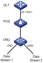
Configuration procedure
# Create ONU 3/0/1:1, and bind it to the ONU.
<Sysname> system-view
[Sysname] interface olt 3/0/1
[Sysname-Olt3/0/1] using onu 1
[Sysname-Olt3/0/1] quit
[Sysname] interface onu 3/0/1:1
[Sysname-Onu3/0/1:1] bind onuid 000f-e200-0104
# Set the uplink bandwidth of the ONU port to 50 Mbps.
[Sysname-Onu3/0/1:1] upstream-sla minimum-bandwidth 800 maximum-bandwidth 800
# Configure the VLAN operation mode as transparent for UNI 1 and UNI 2.
[Sysname-Onu3/0/1:1] uni 1 vlan-mode transparent
[Sysname-Onu3/0/1:1] uni 2 vlan-mode transparent
![]()
For detailed information about ONU uplink bandwidth and VLAN operation mode of a UNI, refer to EPON-OLT in the Access Volume.
# Configure priority remarking for UNI 1 and UNI 2.
[Sysname-Onu3/0/1:1] uni 1 classification-marking index 1 queue 3 priority 3 src-mac equal 000A-EB7F-AAAB
[Sysname-Onu3/0/1:1] uni 2 classification-marking index 1 queue 1 priority 1 src-mac equal 001B-EB7F-21AC
After the configuration above is complete, when two streams (each 50 Mbps) from two UNIs of the ONU are being forwarded to the OLT, the packets sourced from the MAC address of 001B-EB7F-21AC are dropped at forwarding congestion on the ONU port, because the queue precedence of these packets is lower than that of the packets sourced from the MAC address of 000A-EB7F-AAAB.
