- Table of Contents
-
- H3C Data Center Switches M-LAG Configuration Guide-6W101
- 00-M-LAG network planning
- 01-M-LAG+IPv4 and IPv6 Dual-Active VLAN Gateway Configuration Example
- 02-Multi-Layer M-LAG+STP+Dual-Active VLAN Gateway Configuration Examples
- 03-Multi-Layer M-LAG+Dual-Active VLAN Gateway+OSPF Configuration Examples
- 04-Multi-tier M-LAG+Spine Gateways+ECMP Paths to External Network Configuration Example
- 05-M-LAG and VRRP Configuration Example
- 06-M-LAG+RDMA Configuration Example
- 07-M-LAG and EVPN Distributed Gateway (IS-IS for underlay routing) Configuration Example
- 08-M-LAG and EVPN Distributed Gateway (BGP for Underlay Routing) Configuration Example
- 09-M-LAG+EVPN Distributed Gateway (OSPF on Underlay Network)+DHCP Relay+Microsegmentation+Service Chain Configuration Example
- 10-M-LAG+EVPN Centralized Gateway Configuration Example
- 11-Access to M-LAG Through Dynamic Routing and Distributed EVPN Gateways Configuration Example
- 12-M-LAG+EVPN+Monitor Link Configuration Examples
- 13-M-LAG and MVXLAN Configuration Example
- 14-M-LAG and DCI Configuration Example
- 15-M-LAG+EVPN DC Switchover Upon Border Failure Configuration Examples
- 16-Cascaded M-LAG Systems with Attached Multicast Source and Receivers Configuration Examples
- Related Documents
-
| Title | Size | Download |
|---|---|---|
| 16-Cascaded M-LAG Systems with Attached Multicast Source and Receivers Configuration Examples | 364.08 KB |
Example: Setting up two cascaded M-LAG systems with directly attached multicast source and receivers
Configuring the dual-active gateways
Underlay traffic characteristics
Testing network convergence upon single points of failure
Verifying the status of the M-LAG system
Verifying multicast forwarding information
Verifying the traffic interruption time during the upgrade
Replacing a switching fabric module
Configuring the dual-active gateways
Configuring OSPF for establishing Layer 3 connectivity between M-LAG member devices
Underlay traffic characteristics
Testing network convergence upon single points of failure
Verifying the status of the M-LAG system
Verifying routing configuration
Verifying the traffic interruption time during the upgrade
Replacing a switching fabric module
Example: Setting up two cascaded M-LAG systems with directly attached multicast source and receivers
Network configuration
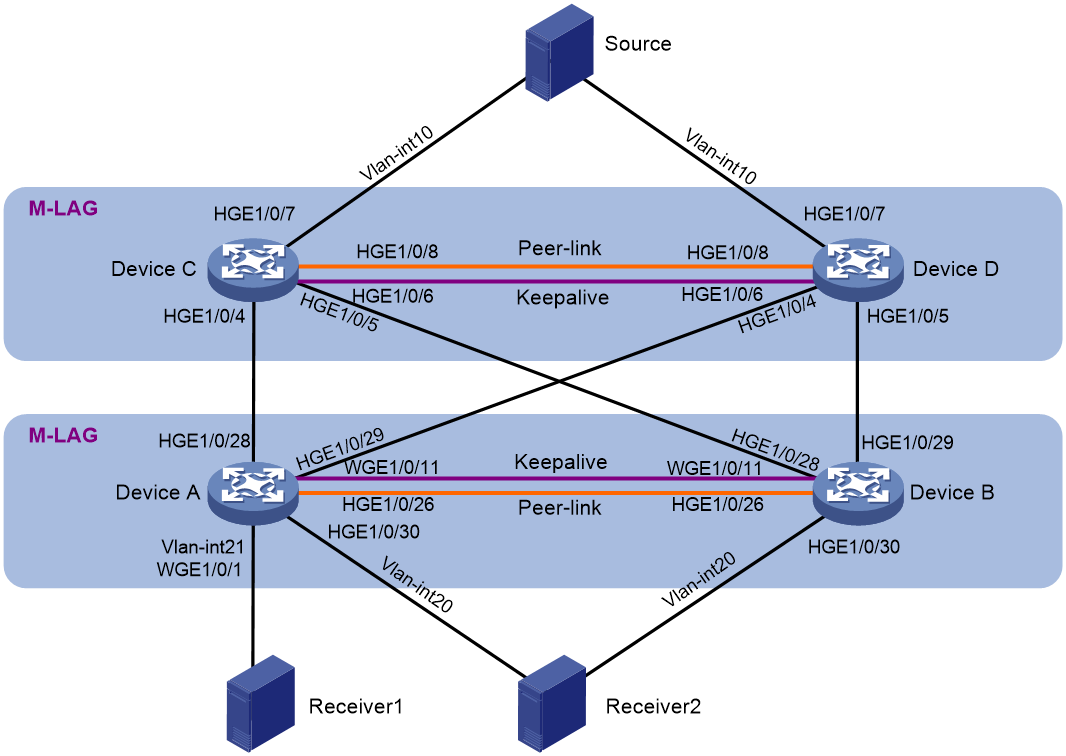
To improve network reliability, set up a two-tier cascaded M-LAG structure to support Layer 3 multicast services, as shown in Figure 1. The receivers receive video-on-demand traffic through multicast. PIM protocol is enabled on each device interface, and the entire PIM domain uses SM non-administrative domain mode.
Multicast receivers can be singlehomed to the receiver side M-LAG member devices or be attached to M-LAG interfaces. The multicast source is connected to an M-LAG system through M-LAG interfaces.
|
Device |
Interface |
IP address |
Peer device and interface |
|
Device A |
WGE1/0/11 |
IPv4: 221.1.2.1/24 |
Device B: WGE1/0/11 |
|
Vlan-int20 |
IPv4: 20.1.1.1/24 |
Receiver 2 |
|
|
Vlan-int21 |
IPv4: 21.1.1.1/24 |
Receiver 1 |
|
|
Loopback0 |
IPv4: 3.3.3.3/32 |
N/A |
|
|
HGE1/0/28 |
IPv4: 11.2.1.2/24 |
Device C: HGE1/0/4 |
|
|
HGE1/0/29 |
IPv4: 12.2.1.2/24 |
Device D: HGE1/0/4 |
|
|
Device B |
WGE1/0/11 |
IPv4: 221.1.2.2/24 |
Device A: WGE1/0/11 |
|
Vlan-int20 |
IPv4: 20.1.1.1/24 |
Receiver 2 |
|
|
Loopback0 |
IPv4: 4.4.4.4/32 |
N/A |
|
|
HGE1/0/28 |
IPv4: 11.3.1.2/24 |
Device C: HGE1/0/5 |
|
|
HGE1/0/29 |
IPv4: 12.3.1.2/24 |
Device D: HGE1/0/5 |
|
|
Device C |
HGE1/0/6 |
IPv4: 220.1.1.1/24 |
Device D: HGE1/0/6 |
|
Vlan-int10 |
IPv4: 10.1.1.1/24 |
Source |
|
|
Loopback0 |
IPv4: 1.1.1.1/32 |
N/A |
|
|
HGE1/0/4 |
IPv4: 11.2.1.1/24 |
Device A: HGE1/0/28 |
|
|
HGE1/0/5 |
IPv4: 11.3.1.1/24 |
Device B: HGE1/0/28 |
|
|
Device D |
HGE1/0/6 |
IPv4: 220.1.1.2/24 |
Device C: HGE1/0/6 |
|
Vlan-int10 |
IPv4: 10.1.1.1/24 |
Source |
|
|
Loopback0 |
IPv4: 2.2.2.2/32 |
N/A |
|
|
HGE1/0/4 |
IPv4: 12.2.1.1/24 |
Device A: HGE1/0/29 |
|
|
HGE1/0/5 |
IPv4: 12.3.1.1/24 |
Device B: HGE1/0/29 |
Applicable product matrix
|
|
IMPORTANT: In addition to running an applicable software version, you must also install the most recent patch, if any. |
|
Device |
Software version |
|
S6805, S6825, S6850, S9850 |
R6710 |
|
S9820-64H, S9820-8C |
Not supported |
|
S6800, S6860, S6900 |
Not supported |
|
S12500X-AF, S12500F-AF, S6890 |
R2825 |
|
S12500R |
Not supported |
|
S12500G-AF |
R7625 |
|
S6812, S6813 |
F6628P22 |
Analysis
· Set up one M-LAG system with Device A and Device B and another with Device C and Device D.
· Create one VLAN interface for the same VLAN on Device A and Device B, respectively. In this example, create VLAN-interface 20. Allocate the same IPv4 addresses and MAC address to the VLAN interfaces for them to act as gateway interfaces. Assign M-LAG interfaces to the VLAN of the VLAN interfaces.
· Create one VLAN interface for the same VLAN on Device C and Device D, respectively. In this example, create VLAN-interface 10. Allocate the same IPv4 addresses and MAC address to the VLAN interfaces for them to act as gateway interfaces. Assign M-LAG interfaces to the VLAN of the VLAN interfaces.
· Enable IP multicast forwarding and IGMP snooping on Device A through Device D. A device with IGMP snooping enabled forwards multicast traffic of known multicast groups to the designated receivers instead of broadcasting the multicast traffic. Configure PIM on interfaces of the devices.
· Create VLAN-interface 21 on Device A to accommodate Receiver 1, which is singlehomed to the device.
Procedure summary
· Configuring the dual-active gateways
· Configuring Layer 3 multicast
Configuring M-LAG
|
|
NOTE: For the S12500X-AF, S12500F-AF, and S6890 series switches, first configure the MAC base address, and then assign MAC addresses on each device in the M-LAG systems based on the MAC base address. For more information about MAC address configuration, see M-LAG network planning. |
Configuring Device A and Device B
|
Device A |
Device B |
Description |
Remarks |
|
m-lag system-mac 1-1-2 |
m-lag system-mac 1-1-2 |
Configure the M-LAG system MAC address. |
You must configure the same M-LAG system MAC address for devices in the same M-LAG system. |
|
m-lag system-number 1 |
m-lag system-number 2 |
Set the M-LAG system number. |
You must set different M-LAG system numbers for devices in the same M-LAG system. |
|
m-lag system-priority 122 |
m-lag system-priority 122 |
Set the M-LAG system priority. |
You must set the same M-LAG system priority for devices in the same M-LAG system. |
|
m-lag standalone enable |
m-lag standalone enable |
Enable M-LAG standalone mode. |
N/A |
|
m-lag keepalive ip destination 221.1.2.2 source 221.1.2.1 |
m-lag keepalive ip destination 221.1.2.1 source 221.1.2.2 |
Configure the destination and source IP addresses of keepalive packets. |
N/A |
|
interface Twenty-FiveGigE1/0/11 |
interface Twenty-FiveGigE1/0/11 |
Enter the view of the interface used for setting up the keepalive link. |
N/A |
|
port link-mode route |
port link-mode route |
Configure the keepalive link interface to operate in route mode as a Layer 3 interface. |
N/A |
|
ip address 221.1.2.1 24 |
ip address 221.1.2.2 24 |
Assign an IP address to the keepalive link interface. |
N/A |
|
quit |
quit |
Return to system view. |
N/A |
|
m-lag mad exclude interface Twenty-FiveGigE1/0/11 |
m-lag mad exclude interface Twenty-FiveGigE1/0/11 |
Exclude the interface used for M-LAG keepalive detection from the shutdown action by M-LAG MAD. |
N/A |
|
interface HundredGigE1/0/28 |
interface HundredGigE1/0/28 |
Enter Ethernet interface view. |
N/A |
|
port link-mode route |
port link-mode route |
Configure the Ethernet interface to operate in route mode as a Layer 3 interface. |
N/A |
|
ip address 11.2.1.2/24 |
ip address 11.3.1.2/24 |
Assign an IP address to the interface. |
N/A |
|
quit |
quit |
Return to system view. |
N/A |
|
interface HundredGigE1/0/29 |
interface HundredGigE1/0/29 |
Enter Ethernet interface view. |
N/A |
|
port link-mode route |
port link-mode route |
Configure the Ethernet interface to operate in route mode as a Layer 3 interface. |
N/A |
|
ip address 12.2.1.2/24 |
ip address 12.3.1.2/24 |
Assign an IP address to the interface. |
N/A |
|
quit |
quit |
Return to system view. |
N/A |
|
m-lag mad exclude interface HundredGigE1/0/28 |
m-lag mad exclude interface HundredGigE1/0/28 |
Exclude an interface-facing a peer M-LAG system from the shutdown action by M-LAG MAD. |
N/A |
|
m-lag mad exclude interface HundredGigE1/0/29 |
m-lag mad exclude interface HundredGigE1/0/29 |
Exclude an interface-facing a peer M-LAG system from the shutdown action by M-LAG MAD. |
N/A |
|
interface bridge-aggregation 1000 |
interface bridge-aggregation 1000 |
Create the Layer 2 aggregate interface to be used as the peer-link interface and enter Layer 2 aggregate interface view. |
N/A |
|
quit |
quit |
Return to system view. |
N/A |
|
Interface HundredGigE 1/0/26 |
interface HundredGigE 1/0/26 |
Enter the view of a physical interface used for setting up the peer link. |
N/A |
|
port link-aggregation group 1000 |
port link-aggregation group 1000 |
Assign the physical interface to the aggregation group of the peer link. |
N/A |
|
quit |
quit |
Return to system view. |
N/A |
|
interface bridge-aggregation 1000 |
interface bridge-aggregation 1000 |
Enter the view of the aggregation group for the peer link. |
N/A |
|
undo mac-address static source-check enable |
undo mac-address static source-check enable |
Disable source MAC check on the interface. |
N/A |
|
link-aggregation mode dynamic |
link-aggregation mode dynamic |
Configure the peer-link aggregate interface to operate in dynamic mode. |
N/A |
|
port m-lag peer-link 1 |
port m-lag peer-link 1 |
Specify the aggregate interface as the peer-link interface. |
N/A |
|
quit |
quit |
Return to system view. |
N/A |
|
interface bridge-aggregation 1 |
interface bridge-aggregation 1 |
Create an aggregate interface. |
N/A |
|
link-aggregation mode dynamic |
link-aggregation mode dynamic |
Configure the aggregate interface to operate in dynamic mode. |
N/A |
|
port m-lag group 1 |
port m-lag group 1 |
Assign the aggregate interface to M-LAG group 1. |
N/A |
|
quit |
quit |
Return to system view. |
N/A |
|
interface HundredGigE1/0/30 |
interface HundredGigE1/0/30 |
Enter Ethernet interface view. |
N/A |
|
port link-aggregation group 1 |
port link-aggregation group 1 |
Assign the interface to the aggregation group of an M-LAG interface. |
N/A |
|
quit |
quit |
Return to system view. |
N/A |
Configuring Device C and Device D
|
Device C |
Device D |
Description |
Remarks |
|
m-lag system-mac 1-1-1 |
m-lag system-mac 1-1-1 |
Configure the M-LAG system MAC address. |
You must configure the same M-LAG system MAC address for devices in the same M-LAG system. |
|
m-lag system-number 1 |
m-lag system-number 2 |
Set the M-LAG system number. |
You must set different M-LAG system numbers for devices in the same M-LAG system. |
|
m-lag system-priority 121 |
m-lag system-priority 121 |
Set the M-LAG system priority. |
You must set the same M-LAG system priority for devices in the same M-LAG system. |
|
m-lag standalone enable |
m-lag standalone enable |
Enable M-LAG standalone mode. |
N/A |
|
m-lag keepalive ip destination 220.1.1.2 source 220.1.1.1 |
m-lag keepalive ip destination 220.1.1.1 source 220.1.1.2 |
Configure the destination and source IP addresses of keepalive packets. |
N/A |
|
interface HundredGigE1/0/6 |
interface HundredGigE1/0/6 |
Enter the view of the interface used for setting up the keepalive link. |
N/A |
|
port link-mode route |
port link-mode route |
Configure the keepalive link interface to operate in route mode as a Layer 3 interface. |
N/A |
|
ip address 220.1.1.1 24 |
ip address 220.1.1.2 24 |
Assign an IP address to the keepalive link interface. |
N/A |
|
quit |
quit |
Return to system view. |
N/A |
|
m-lag mad exclude interface HundredGigE1/0/6 |
m-lag mad exclude interface HundredGigE1/0/6 |
Exclude the interface used for M-LAG keepalive detection from the shutdown action by M-LAG MAD. |
N/A |
|
interface HundredGigE1/0/4 |
interface HundredGigE1/0/4 |
Enter Ethernet interface view. |
N/A |
|
port link-mode route |
port link-mode route |
Configure the Ethernet interface to operate in route mode as a Layer 3 interface. |
N/A |
|
ip address 11.2.1.1/24 |
ip address 11.3.1.1/24 |
Assign an IP address to the interface. |
N/A |
|
quit |
quit |
Return to system view. |
N/A |
|
interface HundredGigE1/0/5 |
interface HundredGigE1/0/5 |
Enter Ethernet interface view. |
N/A |
|
port link-mode route |
port link-mode route |
Configure the Ethernet interface to operate in route mode as a Layer 3 interface. |
N/A |
|
ip address 12.2.1.1/24 |
ip address 12.3.1.1/24 |
Assign an IP address to the interface. |
N/A |
|
quit |
quit |
Return to system view. |
N/A |
|
m-lag mad exclude interface HundredGigE1/0/4 |
m-lag mad exclude interface HundredGigE1/0/4 |
Exclude an interface-facing a peer M-LAG system from the shutdown action by M-LAG MAD. |
N/A |
|
m-lag mad exclude interface HundredGigE1/0/5 |
m-lag mad exclude interface HundredGigE1/0/5 |
Exclude an interface-facing a peer M-LAG system from the shutdown action by M-LAG MAD. |
N/A |
|
interface bridge-aggregation 1000 |
interface bridge-aggregation 1000 |
Create the Layer 2 aggregate interface to be used as the peer-link interface and enter Layer 2 aggregate interface view. |
N/A |
|
quit |
quit |
Return to system view. |
N/A |
|
Interface HundredGigE 1/0/8 |
interface HundredGigE 1/0/8 |
Enter the view of a physical interface used for setting up the peer link. |
N/A |
|
port link-aggregation group 1000 |
port link-aggregation group 1000 |
Assign the physical interface to the aggregation group of the peer link. |
N/A |
|
quit |
quit |
Return to system view. |
N/A |
|
interface bridge-aggregation 1000 |
interface bridge-aggregation 1000 |
Enter the view of the aggregation group for the peer link. |
N/A |
|
undo mac-address static source-check enable |
undo mac-address static source-check enable |
Disable source MAC check on the interface. |
N/A |
|
link-aggregation mode dynamic |
link-aggregation mode dynamic |
Configure the peer-link aggregate interface to operate in dynamic mode. |
N/A |
|
port m-lag peer-link 1 |
port m-lag peer-link 1 |
Configure the aggregate interface as the peer-link interface. |
N/A |
|
quit |
quit |
Return to system view. |
N/A |
|
interface bridge-aggregation 1 |
interface bridge-aggregation 1 |
Create an aggregate interface. |
N/A |
|
link-aggregation mode dynamic |
link-aggregation mode dynamic |
Configure the aggregate interface to operate in dynamic mode. |
N/A |
|
port m-lag group 1 |
port m-lag group 1 |
Assign the aggregate interface to M-LAG group 1. |
N/A |
|
quit |
quit |
Return to system view. |
N/A |
|
interface HundredGigE 1/0/7 |
interface HundredGigE 1/0/7 |
Enter Ethernet interface view. |
N/A |
|
port link-aggregation group 1 |
port link-aggregation group 1 |
Assign the interface to the aggregation group of an M-LAG interface. |
N/A |
|
quit |
quit |
Return to system view. |
N/A |
Configuring the dual-active gateways
|
|
NOTE: For the S12500X-AF, S12500F-AF, and S6890 series switches, first configure the MAC base address, and then assign MAC addresses on each device in the M-LAG systems based on the MAC base address. For more information about MAC address configuration, see M-LAG network planning. |
Configuring Device A and Device B
|
Device A |
Device B |
Description |
|
vlan 20 |
vlan 20 |
Create VLAN 20. |
|
interface bridge-aggregation 1 |
interface bridge-aggregation 1 |
Enter aggregate interface view. |
|
port link-type trunk |
port link-type trunk |
Set the link type of the Layer 2 aggregate interface to trunk. |
|
port trunk permit vlan 20 |
port trunk permit vlan 20 |
Assign the interface to VLAN 20. |
|
undo port trunk permit vlan 1 |
undo port trunk permit vlan 1 |
Remove the interface from VLAN 1. |
|
quit |
quit |
Return to system view. |
|
interface vlan-interface 20 |
interface vlan-interface 20 |
Create VLAN-interface 20. |
|
ip address 20.1.1.1 255.255.255.0 |
ip address 20.1.1.1 255.255.255.0 |
Assign an IPv4 address to VLAN-interface 20. |
|
mac-address 0020-0020-0020 |
mac-address 0020-0020-0020 |
Assign a MAC address to VLAN-interface 20. |
|
quit |
quit |
Return to system view. |
|
m-lag mad exclude interface Vlan-interface20 |
m-lag mad exclude interface Vlan-interface20 |
Exclude VLAN-interface 20 from the shutdown action by M-LAG MAD. |
|
vlan 21 |
- |
Create VLAN 21. |
|
interface Twenty-FiveGigE1/0/1 |
- |
Enter Ethernet interface view. |
|
port link-type trunk |
- |
Set the link type of the interface to trunk. |
|
port trunk permit vlan 21 |
- |
Assign the interface to VLAN 21. |
|
undo port trunk permit vlan 1 |
- |
Remove the interface from VLAN 1. |
|
quit |
- |
Return to system view. |
|
interface vlan-interface 21 |
- |
Create VLAN-interface 21. |
|
ip address 21.1.1.1 255.255.255.0 |
- |
Assign an IPv4 address to VLAN-interface 21. |
|
mac-address 0020-0020-0021 |
- |
Assign a MAC address to VLAN-interface 21. |
|
quit |
- |
Return to system view. |
|
m-lag mad exclude interface Vlan-interface21 |
- |
Exclude VLAN-interface 21 from the shutdown action by M-LAG MAD. |
Configuring Device C and Device D
|
Device C |
Device D |
Description |
|
vlan 10 |
vlan 10 |
Create VLAN 10. |
|
interface bridge-aggregation 1 |
interface bridge-aggregation 1 |
Enter aggregate interface view. |
|
port link-type trunk |
port link-type trunk |
Set the link type of the Layer 2 aggregate interface to trunk. |
|
port trunk permit vlan 10 |
port trunk permit vlan 10 |
Assign the interface to VLAN 10. |
|
undo port trunk permit vlan 1 |
undo port trunk permit vlan 1 |
Remove the interface from VLAN 1. |
|
quit |
quit |
Return to system view. |
|
interface vlan-interface 10 |
interface vlan-interface 10 |
Create VLAN-interface 10. |
|
ip address 10.1.1.1 255.255.255.0 |
ip address 10.1.1.1 255.255.255.0 |
Assign an IPv4 address to VLAN-interface 10. |
|
mac-address 0010-0010-0010 |
mac-address 0010-0010-0010 |
Assign a MAC address to VLAN-interface 10. |
|
quit |
quit |
Return to system view. |
|
m-lag mad exclude interface Vlan-interface10 |
m-lag mad exclude interface Vlan-interface10 |
Exclude VLAN-interface 10 from the shutdown action by M-LAG MAD. |
Configuring Layer 3 multicast
Configuring Device A and Device B
|
Device A |
Device B |
Description |
|
multicast routing |
multicast routing |
Enable IP multicast routing. |
|
igmp-snooping |
igmp-snooping |
Enable IGMP snooping. |
|
Vlan 20 |
Vlan 20 |
Enter VLAN view. |
|
igmp-snooping enable |
igmp-snooping enable |
Enable IGMP snooping in the VLAN. |
|
interface Vlan-interface20 |
interface Vlan-interface20 |
Enable VLAN interface view. |
|
pim sm |
pim sm |
Enable PIM SM. |
|
igmp enable |
igmp enable |
Enable IGMP. |
|
pim distributed-dr |
pim distributed-dr |
Configure the interface as a DR interface to forward multicast traffic. This command is not supported by the S12500X-AF, S12500F-AF, or S6890 switches. |
|
pim passive |
pim passive |
Enable PIM passive mode for the interface to forward multicast traffic. Execute this command only on the S12500X-AF, S12500F-AF, or S6890 switch. |
|
quit |
quit |
Return to the upper-level view. |
|
interface Vlan-interface21 |
- |
Enable VLAN interface view. |
|
pim sm |
- |
Enable PIM SM. |
|
igmp enable |
- |
Enable IGMP. |
|
quit |
- |
Return to the upper-level view. |
|
interface HundredGigE1/0/28 |
interface HundredGigE1/0/28 |
Enter Ethernet interface view. |
|
pim sm |
pim sm |
Enable PIM SM. |
|
quit |
quit |
Return to the upper-level view. |
|
interface HundredGigE1/0/29 |
interface HundredGigE1/0/29 |
Enter Ethernet interface view. |
|
pim sm |
pim sm |
Enable PIM SM. |
|
quit |
quit |
Return to the upper-level view. |
|
interface LoopBack0 |
interface LoopBack0 |
Enter loopback interface view. |
|
pim sm |
pim sm |
Enable PIM SM. |
|
quit |
quit |
Return to the upper-level view. |
|
interface Twenty-FiveGigE1/0/11 |
interface Twenty-FiveGigE1/0/11 |
Enter Ethernet interface view. |
|
pim sm |
pim sm |
Enable PIM SM. |
|
quit |
quit |
Return to the upper-level view. |
|
pim |
pim |
Enter PIM view. |
|
static-rp 4.4.4.4 |
static-rp 4.4.4.4 |
Configure a static RP. |
Configuring Device C and Device D
|
Device C |
Device D |
Description |
|
multicast routing |
multicast routing |
Enable IP multicast routing. |
|
igmp-snooping |
igmp-snooping |
Enable IGMP snooping. |
|
Vlan 10 |
Vlan 10 |
Enter VLAN view. |
|
igmp-snooping enable |
igmp-snooping enable |
Enable IGMP snooping in the VLAN. |
|
quit |
quit |
Return to the upper-level view. |
|
interface Vlan-interface10 |
interface Vlan-interface10 |
Enable VLAN interface view. |
|
pim sm |
pim sm |
Enable PIM SM. |
|
pim distributed-dr |
pim distributed-dr |
Configure the interface as a DR interface to forward multicast traffic. This command is not supported by the S12500X-AF, S12500F-AF, or S6890 switches. |
|
pim passive |
pim passive |
Enable PIM passive mode for the interface to forward multicast traffic. Execute this command only on the S12500X-AF, S12500F-AF, or S6890 switch. |
|
quit |
quit |
Return to the upper-level view. |
|
interface HundredGigE1/0/4 |
interface HundredGigE1/0/4 |
Enter Ethernet interface view. |
|
pim sm |
pim sm |
Enable PIM SM. |
|
quit |
quit |
Return to the upper-level view. |
|
interface HundredGigE1/0/5 |
interface HundredGigE1/0/5 |
Enter Ethernet interface view. |
|
pim sm |
pim sm |
Enable PIM SM. |
|
quit |
quit |
Return to the upper-level view. |
|
interface LoopBack0 |
interface LoopBack0 |
Enter loopback interface view. |
|
pim sm |
pim sm |
Enable PIM SM. |
|
quit |
quit |
Return to the upper-level view. |
|
interface HundredGigE1/0/6 |
interface HundredGigE1/0/6 |
Enter Ethernet interface view. |
|
pim sm |
pim sm |
Enable PIM SM. |
|
quit |
quit |
Return to the upper-level view. |
|
pim |
pim |
Enter PIM view. |
|
static-rp 4.4.4.4 |
static-rp 4.4.4.4 |
Configure a static RP. |
Traffic forwarding models
Underlay traffic characteristics
The forwarding model matrix provides the following characteristics of underlay traffic:
· No.—Traffic number in the U-X-XXX format:
¡ U—Underlay traffic.
¡ X—Protocol number, which can be 4 (IPv4)
¡ XXX—Traffic sequence number.
· Traffic type—Type of underlay traffic, which can only be IPv4 known multicast
· Direction—Direction of underlay traffic. The value is south-north, which indicates traffic from the south to north.
· Forwarding path—Nodes that underlay traffic traverses.
· Traffic simulation—Traffic simulation method. Typically, a tester is used to simulate server traffic.
· Load—Traffic size, which can be light (less than 1000 flows) and heavy (more than 1000 flows).
· Traffic direction to firewalls/LB—No firewalls or LBs are used in this example. This field is not involved.
Forwarding models
|
No. |
Traffic type |
Direction |
Forwarding path |
Traffic simulation |
Load |
Traffic direction to firewalls/LB |
|
U-4-101 |
IPv4 known multicast |
South-north |
100 multicast groups Source > Device C and Device D > Device A and Device B > Receiver 2 |
Tester |
Light |
N/A |
|
U-4-102 |
IPv4 known mutlicsat |
South-north |
100 multicast groups Source > Device C and Device D > Device A and Device B > Receiver 1 |
Tester |
Light |
N/A |
Testing network convergence upon single points of failure
Table 1 Network convergence upon single points of failure
|
Device |
Failure type |
Traffic interruption time (U-4-101/U-4-102) |
|
M-LAG |
Multicast source-side single point of failure on M-LAG member links |
≤ 100 ms |
|
Multicast source-side single point of failure restored on M-LAG member links |
≤ 100 ms |
|
|
Multicast source-side peer link failure |
≤ 500 ms |
|
|
Multicast source-side peer link failure restored |
≤ 100 ms |
|
|
Multicast source-side keepalive link failure |
0 ms |
|
|
Multicast source-side keepalive link failure restored |
0 ms |
|
|
Multicast source-side keepalive link and peer link failure |
≤ 500 ms |
|
|
Multicast source-side keepalive link and peer link failure restored |
≤ 500 ms |
|
|
Single ECMP link failure between the M-LAG systems |
≤ 500 ms/1000 ms |
|
|
Single ECMP link restored between the M-LAG systems |
≤ 100 ms |
|
|
Multicast-receiver side single point of failure on M-LAG member links |
≤ 100 ms/0 ms |
|
|
Multicast-receiver side single point of failure restored on M-LAG member links |
≤ 100 ms/0 ms |
|
|
Multicast-receiver side peer link failure |
≤ 100 ms/0 ms |
|
|
Multicast-receiver side peer link failure restored |
≤ 100 ms/0 ms |
|
|
Multicast-receiver side keepalive link failure |
0 ms |
|
|
Multicast-receiver side keepalive link failure restored |
0 ms |
|
|
Multicast-receiver side keepalive link and peer link failure |
≤ 500 ms/0 ms |
|
|
Multicast-receiver side keepalive link and peer link restored |
≤ 500 ms/0 ms |
|
|
Upgrade |
≤ 10000 ms (upgrade the M-LAG member devices one after another) |
|
|
Hardware replacement |
Fixed-port device replacement: ≤ 10000 ms |
Verifying the configuration
Verifying the status of the M-LAG system
Verify that the M-LAG system is working correctly on Device A and Device B. Use Device A as an example. The verification procedure is the same for Device B, Device C, and Device D.
# Display summary information about the peer-link interface and M-LAG interface.
[Device A]display m-lag summary
Flags: A -- Aggregate interface down, B -- No peer M-LAG interface configured
C -- Configuration consistency check failed
Peer-link interface: BAGG1000
Peer-link interface state (cause): UP
Keepalive link state (cause): UP
M-LAG interface information
M-LAG IF M-LAG group Local state (cause) Peer state Remaining down time(s)
BAGG1 1 UP UP -
# Verify that keepalive link is working correctly.
[Device A]display m-lag keepalive
Neighbor keepalive link status (cause): Up
Neighbor is alive for: 256 s 620 ms
Keepalive packet transmission status:
Sent: Successful
Received: Successful
Last received keepalive packet information:
Source IP address: 221.1.2.2
Time: 2023/06/13 05:00:51
Action: Accept
M-LAG keepalive parameters:
Destination IP address: 221.1.2.2
Source IP address: 221.1.2.1
Keepalive UDP port : 6400
Keepalive VPN name : N/A
Keepalive interval : 1000 ms
Keepalive timeout : 5 sec
Keepalive hold time: 3 sec
# Display the M-LAG system information.
[Device A]display m-lag system
System information
Local system number: 1 Peer system number: 2
Local system MAC: 0001-0001-0002 Peer system MAC: 0001-0001-0002
Local system priority: 122 Peer system priority: 122
Local bridge MAC: dcda-8037-2bc0 Peer bridge MAC: bc22-4720-d5b9
Local effective role: Secondary Peer effective role: Primary
Health level: 0
Standalone mode on split: Enabled
In standalone mode: No
System timer information
Timer State Value (s) Remaining time (s)
Auto recovery Disabled - -
Restore delay Disabled 60 -
Consistency-check delay Disabled 30 -
Standalone delay Disabled 0 -
Role to None delay Disabled 60 -
# Display detailed information about the peer-link interface and M-LAG interfaces.
[Device A]display m-lag verbose
Flags: A -- Home_Gateway, B -- Neighbor_Gateway, C -- Other_Gateway,
D -- PeerLink_Activity, E -- DRCP_Timeout, F -- Gateway_Sync,
G -- Port_Sync, H -- Expired
Peer-link interface/Peer-link interface ID: BAGG1000/1
State: UP
Cause: -
Local DRCP flags/Peer DRCP flags: ABDFG/ABDFG
Local Selected ports (index): HGE1/0/26 (30)
Peer Selected ports indexes: 225
M-LAG interface/M-LAG group ID: BAGG1/1
Local M-LAG interface state: UP
Peer M-LAG interface state: UP
M-LAG group state: UP
Local M-LAG interface down cause: -
Remaining M-LAG DOWN time: -
Local M-LAG interface LACP MAC: Config=N/A, Effective=0001-0001-0002
Peer M-LAG interface LACP MAC: Config=N/A, Effective=0001-0001-0002
Local M-LAG interface LACP priority: Config=32768, Effective=122
Peer M-LAG interface LACP priority: Config=32768, Effective=122
Local DRCP flags/Peer DRCP flags: ABDFG/ABDFG
Local Selected ports (index): HGE1/0/30 (50)
Peer Selected ports indexes: 245
Verifying multicast forwarding information
# Verify that PIM neighbor relationships are established correctly.
[Device A]display pim neighbor
Total Number of Neighbors = 3
Neighbor Interface Uptime Expires DR-Priority Mode
221.1.2.2 WGE1/0/11 00:06:12 00:01:37 1 P
11.2.1.1 HGE1/0/28 2d:00h 00:01:44 1 P
12.2.1.1 HGE1/0/29 00:15:52 00:01:44 1 P
[Device B]display pim neighbor
Total Number of Neighbors = 3
Neighbor Interface Uptime Expires DR-Priority Mode
221.1.2.1 WGE1/0/11 00:06:40 00:01:35 1 P
11.3.1.1 HGE1/0/28 2d:00h 00:01:44 1 P
12.3.1.1 HGE1/0/29 2d:00h 00:01:32 1 P
[Device C]display pim neighbor
Total Number of Neighbors = 3
Neighbor Interface Uptime Expires DR-Priority Mode
11.2.1.2 HGE1/0/4 2d:00h 00:01:42 1 P
11.3.1.2 HGE1/0/5 2d:00h 00:01:27 1 P
220.1.1.2 HGE1/0/6 00:19:34 00:01:37 1 P
[Device D]display pim neighbor
Total Number of Neighbors = 3
Neighbor Interface Uptime Expires DR-Priority Mode
12.2.1.2 HGE1/0/4 00:16:32 00:01:26 1 P
12.3.1.2 HGE1/0/5 2d:00h 00:01:20 1 P
220.1.1.1 HGE1/0/6 00:19:38 00:01:26 1 P
# Verify that multicast forwarding entries are created correctly.
[Device A]dis igmp group
IGMP groups in total: 200
Vlan-interface20(20.1.1.1):
IGMP groups reported in total: 100
Group address Last reporter Uptime Expires
225.0.0.1 20.1.1.2 00:07:34 00:03:04
225.0.0.2 20.1.1.2 00:07:26 00:03:03
225.0.0.3 20.1.1.2 00:07:30 00:03:07
225.0.0.98 20.1.1.2 00:07:28 00:03:07
225.0.0.99 20.1.1.2 00:07:27 00:03:10
225.0.0.100 20.1.1.2 00:07:26 00:03:06
Vlan-interface21(21.1.1.1):
IGMP groups reported in total: 100
Group address Last reporter Uptime Expires
226.0.0.1 21.1.1.2 00:32:50 00:04:17
226.0.0.2 21.1.1.2 00:32:50 00:02:12
226.0.0.3 21.1.1.2 00:32:50 00:02:12
226.0.0.98 21.1.1.2 00:32:50 00:04:15
226.0.0.99 21.1.1.2 00:32:50 00:04:18
226.0.0.100 21.1.1.2 00:32:50 00:02:11
# Verify that PIM routing entries are created correctly.
[Device A]dis pim routing-table
Total 200 (*, G) entries; 200 (S, G) entries
(*, 225.0.0.1)
RP: 4.4.4.4
Protocol: pim-sm, Flag: WC
UpTime: 00:08:57
Upstream interface: HundredGigE1/0/29
Upstream neighbor: 12.2.1.1
RPF prime neighbor: 12.2.1.1
Downstream interface information:
Total number of downstream interfaces: 1
1: Vlan-interface20
Protocol: igmp, UpTime: 00:08:57, Expires: -
(10.1.1.2, 225.0.0.1)
RP: 4.4.4.4
Protocol: pim-sm, Flag: SPT ACT 2MVPN
UpTime: 00:41:07
Upstream interface: HundredGigE1/0/29
Upstream neighbor: 12.2.1.1
RPF prime neighbor: 12.2.1.1
Downstream interface information:
Total number of downstream interfaces: 1
1: Vlan-interface20
Protocol: pim-sm, UpTime: 00:08:57, Expires: -
(*, 226.0.0.1)
RP: 4.4.4.4
Protocol: pim-sm, Flag: WC
UpTime: 00:34:27
Upstream interface: HundredGigE1/0/29
Upstream neighbor: 12.2.1.1
RPF prime neighbor: 12.2.1.1
Downstream interface information:
Total number of downstream interfaces: 1
1: Vlan-interface21
Protocol: igmp, UpTime: 00:34:27, Expires: -
(10.1.1.2, 226.0.0.1)
RP: 4.4.4.4
Protocol: pim-sm, Flag: SPT ACT 2MVPN
UpTime: 00:37:01
Upstream interface: HundredGigE1/0/29
Upstream neighbor: 12.2.1.1
RPF prime neighbor: 12.2.1.1
Downstream interface information:
Total number of downstream interfaces: 1
1: Vlan-interface21
Protocol: pim-sm, UpTime: 00:34:27, Expires: -
[Device B]display pim routing-table
Total 200 (*, G) entries; 201 (S, G) entries
(*, 225.0.0.1)
RP: 4.4.4.4 (local)
Protocol: pim-sm, Flag: WC
UpTime: 00:15:09
Upstream interface: Register-Tunnel0
Upstream neighbor: NULL
RPF prime neighbor: NULL
Downstream interface information:
Total number of downstream interfaces: 2
1: HundredGigE1/0/29
Protocol: pim-sm, UpTime: 00:10:02, Expires: 00:03:28
2: Vlan-interface20
Protocol: igmp, UpTime: 00:15:09, Expires: -
(10.1.1.2, 225.0.0.1)
RP: 4.4.4.4 (local)
Protocol: pim-sm, Flag: SPT 2MSDP ACT 2MVPN
UpTime: 00:44:11
Upstream interface: HundredGigE1/0/29
Upstream neighbor: 12.3.1.1
RPF prime neighbor: 12.3.1.1
Downstream interface information:
Total number of downstream interfaces: 1
1: Vlan-interface20
Protocol: pim-sm, UpTime: 00:15:09, Expires: -
(*, 226.0.0.1)
RP: 4.4.4.4 (local)
Protocol: pim-sm, Flag: WC
UpTime: 00:23:10
Upstream interface: Register-Tunnel0
Upstream neighbor: NULL
RPF prime neighbor: NULL
Downstream interface information:
Total number of downstream interfaces: 1
1: HundredGigE1/0/29
Protocol: pim-sm, UpTime: 00:20:31, Expires: 00:02:58
(10.1.1.2, 226.0.0.1)
RP: 4.4.4.4 (local)
Protocol: pim-sm, Flag: RPT 2MSDP ACT 2MVPN
UpTime: 00:45:34
Upstream interface: Register-Tunnel0
Upstream neighbor: NULL
RPF prime neighbor: NULL
Downstream interface information: None
Upgrading the devices
Checking the environment
Execute the commands in "Verifying the configuration" and the following commands to verify that the devices are available for an upgrade.
|
M-LAG 1 |
M-LAG 2 |
Description |
|
display device |
display device |
Displays device information. |
|
display boot-loader |
display boot-loader |
Displays current software images and startup software images. |
|
display version |
display version |
Displays system version information. |
Upgrading the devices
See H3C Switches M-LAG System Upgrade & Replacement & Expansion Guide.
Verifying the traffic interruption time during the upgrade
See "Testing network convergence upon single points of failure."
Verifying the upgrade result
Execute the commands in "Verifying the configuration" and the following commands to verify that the device is upgraded successfully.
|
M-LAG 1 |
M-LAG 2 |
Description |
|
display device |
display device |
Displays device information. |
|
display boot-loader |
display boot-loader |
Displays current software images and startup software images. |
|
display version |
display version |
Displays system version information. |
Replacing hardware
Replacing a service module
Checking the environment
Execute the commands in "Verifying the configuration" and the following commands to verify that the device is available for a replacement.
|
M-LAG 1 |
M-LAG 2 |
Description |
|
display device |
display device |
Displays device information. |
|
display boot-loader |
display boot-loader |
Displays current software images and startup software images. |
|
display version |
display version |
Displays system version information. |
Replacing hardware
Switch service and management traffic on the target service module to other service modules.
Power off the device and replace the service module, or replace the service module when the device is running. For more information, see the installation guides for the service module.
For details, see H3C Switches M-LAG System Upgrade & Replacement & Expansion Guide.
Verifying the traffic interruption time
For more information, see "Testing network convergence upon single points of failure."
Verifying the replacement result
Execute the commands in "Checking the environment."
Replacing a switching fabric module
Checking the environment
Execute the commands in "Verifying the configuration" and the following commands to verify that the device is available for a replacement.
|
M-LAG 1 |
M-LAG 2 |
Description |
|
display device |
display device |
Displays device information. |
|
display boot-loader |
display boot-loader |
Displays current software images and startup software images. |
|
display version |
display version |
Displays system version information. |
Replacing hardware
Power off the device and replace the switching fabric module, or replace the switching fabric module when the device is running. For more information, see the installation guides for the switching fabric module.
Verifying the traffic interruption time
For more information, see "Testing network convergence upon single points of failure."
Verifying the replacement result
Execute the commands in "Checking the environment."
Replace a device
Checking the environment
Execute the commands in "Verifying the configuration" and the following commands to verify that the device is available for a replacement.
|
M-LAG 1 |
M-LAG 2 |
Description |
|
display device |
display device |
Displays device information. |
|
display boot-loader |
display boot-loader |
Displays current software images and startup software images. |
|
display version |
display version |
Displays system version information. |
Replacing hardware
See H3C Switches M-LAG System Upgrade & Replacement & Expansion Guide.
Verifying the traffic interruption time
For more information, see "Testing network convergence upon single points of failure."
Verifying the replacement result
Execute the commands in "Checking the environment."
Example: Setting up two cascaded M-LAG systems with multicast source and receivers attached via intermediate devices
Network configuration
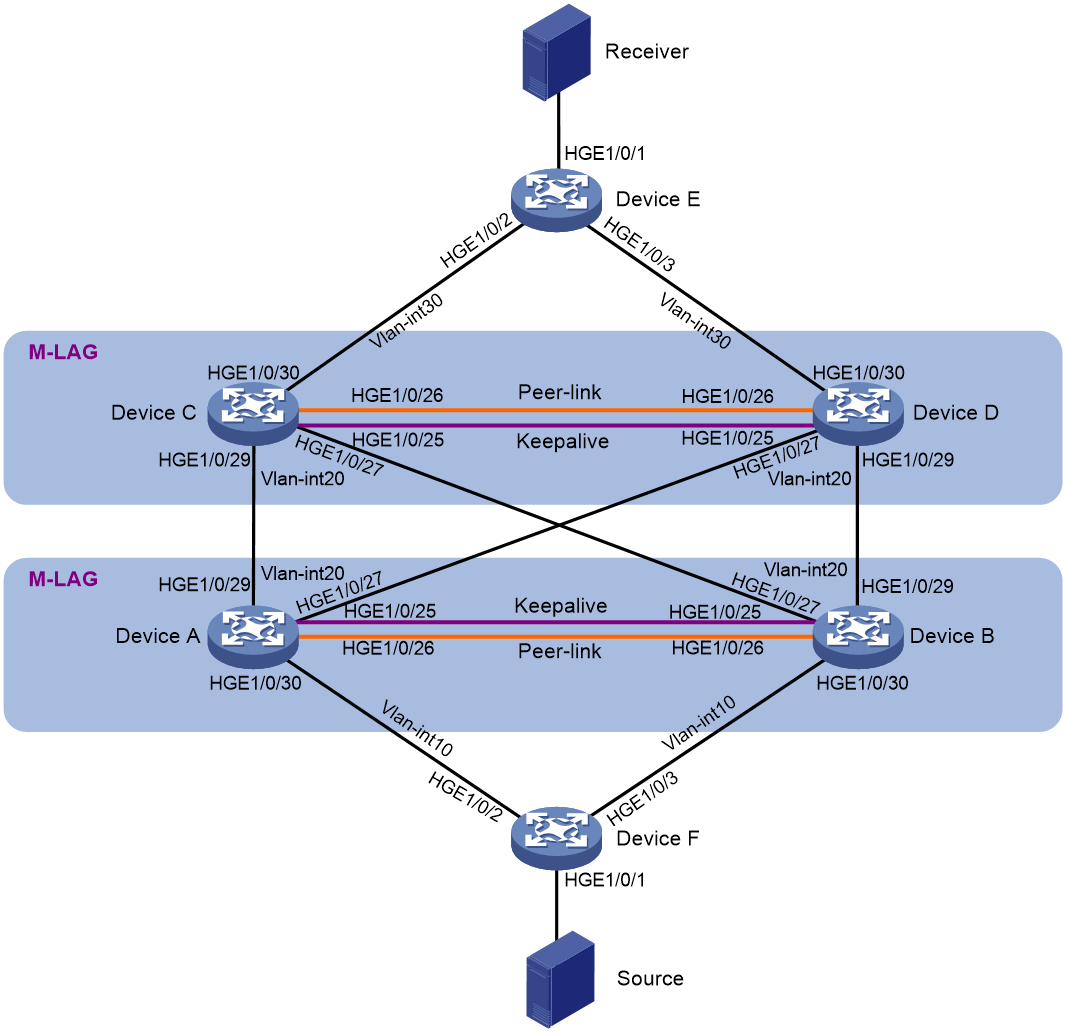
To improve network reliability, set up a two-tier cascaded M-LAG structure to support Layer 3 multicast services, as shown in Figure 2. The receivers receive video-on-demand traffic through multicast. PIM protocol is enabled on each device interface, and the entire PIM domain uses SM non-administrative domain mode.
Configure M-LAG dual-active gateways, and run the OSPF protocol in the network to establish dynamic routing neighbors between the two-tier cascaded M-LAG systems and between the M-LAG systems and user-side devices. OSPF reduces the difficulty of network operation and enhances flexible deployment capabilities.
Enable M-LAG standalone mode and set the priority of aggregate interfaces for the following purposes:
· When an access link fails, traffic can be quickly switched to another link to ensure reliability.
· The two access links can forward user traffic simultaneously to increase bandwidth, and traffic load can be shared between the two access links.
· If multiple link failures cause an M-LAG system to split, M-LAG switches to standalone mode. Only the designated device forwards business traffic to avoid abnormal traffic forwarding.
|
Interface |
IP address |
Peer device and interface |
|
|
Device A |
HGE1/0/25 |
IPv4: 221.1.3.1/24 |
Device B: HGE1/0/25 |
|
Vlan-int10 |
IPv4: 10.1.1.1/24 |
Device F: Vlan-int10 |
|
|
Vlan-int20 |
IPv4: 20.1.1.1/24 |
Device C and Device D: Vlan-int20 |
|
|
Loopback0 |
IPv4: 5.5.5.5/32 |
N/A |
|
|
Device B |
HGE1/0/25 |
IPv4: 221.1.3.2/24 |
Device A: HGE1/0/25 |
|
Vlan-int10 |
IPv4: 10.1.1.1/24 |
Device F: Vlan-int10 |
|
|
Vlan-int20 |
IPv4: 20.1.1.1/24 |
Device C and Device D: Vlan-int20 |
|
|
Loopback0 |
IPv4: 6.6.6.6/32 |
N/A |
|
|
Device C |
HGE1/0/25 |
IPv4: 221.1.2.1/24 |
Device D: HGE1/0/25 |
|
Vlan-int20 |
IPv4: 20.1.1.2/24 |
Device A and Device B: Vlan-int20 |
|
|
Vlan-int30 |
IPv4: 30.1.1.1/24 |
Device E: Vlan-int30 |
|
|
Loopback0 |
IPv4: 3.3.3.3/32 |
N/A |
|
|
Device D |
HGE1/0/25 |
IPv4: 221.1.2.2/24 |
Device C: HGE1/0/25 |
|
Vlan-int20 |
IPv4: 20.1.1.2/24 |
Device A and Device B: Vlan-int20 |
|
|
Vlan-int30 |
IPv4: 30.1.1.1/24 |
Device E: Vlan-int30 |
|
|
Loopback0 |
IPv4: 4.4.4.4/32 |
N/A |
|
|
Device E |
Vlan-int30 |
IPv4: 30.1.1.3/24 |
Device C and Device D: Vlan-int30 |
|
Vlan-int40 |
IPv4: 40.1.0.1/16 |
N/A |
|
|
Loopback0 |
IPv4: 1.1.1.1/32 |
N/A |
|
|
Device F |
Vlan-int10 |
IPv4: 10.1.1.2/24 |
Device A and Device B: Vlan-int10 |
|
Vlan-int50 |
IPv4: 50.1.1.1/24 |
N/A |
|
|
Loopback0 |
IPv4: 2.2.2.2/32 |
N/A |
Applicable product matrix
|
|
IMPORTANT: In addition to running an applicable software version, you must also install the most recent patch, if any. |
|
Device |
Software version |
|
S6805/S6825/S6850/S9850 |
R6710 |
|
S9820-64H/S9820-8C |
Not supported |
|
S6800/S6860/S6900 |
Not supported |
|
S12500X-AF/S12500F-AF/S6890 |
R2825 |
|
S12500R |
Not supported |
|
S12500G-AF |
R7625 |
|
S6812/S6813 |
F6628P22 |
Analysis
· Set up one M-LAG system with Device A and Device B and another with Device C and Device D.
· Create one VLAN interface for the same VLAN on Device A and Device B, respectively. In this example, create VLAN-interface 10. Allocate the same IPv4 addresses and MAC address to the VLAN interfaces for them to act as gateway interfaces. Assign M-LAG interfaces to the VLAN of the VLAN interfaces.
· Create one VLAN interface for the same VLAN on Device C and Device D, respectively. In this example, create VLAN-interface 20. Allocate the same IPv4 addresses and MAC address to the VLAN interfaces for them to act as gateway interfaces. Assign M-LAG interfaces to the VLAN of the VLAN interfaces.
· Assign M-LAG virtual IP addresses to the VLAN interfaces for the M-LAG member devices to set up OSPF neighbor relationships among them and with Device E and Device F.
· Enable IP multicast forwarding and IGMP snooping on Device A through Device F. A device with IGMP snooping enabled forwards multicast traffic of known multicast groups to the designated receivers instead of broadcasting the multicast traffic. Configure PIM on interfaces of the devices.
Procedure summary
· Configuring the dual-active gateways
· Configuring OSPF for establishing Layer 3 connectivity between M-LAG member devices
· Configuring Layer 3 multicast
Configuring M-LAG
|
|
NOTE: For the S12500X-AF, S12500F-AF, and S6890 series switches, first configure the MAC base address, and then assign MAC addresses on each device in the M-LAG systems based on the MAC base address. For more information about MAC address configuration, see M-LAG network planning. |
Configuring Device A and Device B
|
Device A |
Device B |
Description |
Remarks |
|
m-lag system-mac 5-5-5 |
m-lag system-mac 5-5-5 |
Configure the M-LAG system MAC address. |
You must configure the same M-LAG system MAC address for devices in the same M-LAG system. |
|
m-lag system-number 1 |
m-lag system-number 2 |
Set the M-LAG system number. |
You must set different M-LAG system numbers for devices in the same M-LAG system. |
|
m-lag system-priority 123 |
m-lag system-priority 123 |
Set the M-LAG system priority. |
You must set the same M-LAG system priority for devices in the same M-LAG system. |
|
m-lag standalone enable |
m-lag standalone enable |
Enable M-LAG standalone mode. |
N/A |
|
m-lag keepalive ip destination 221.1.3.2 source 221.1.3.1 |
m-lag keepalive ip destination 221.1.3.1 source 221.1.3.2 |
Configure the destination and source IP addresses of keepalive packets. |
N/A |
|
interface HundredGigE 1/0/25 |
interface HundredGigE 1/0/25 |
Enter the view of the interface used for setting up the keepalive link. |
N/A |
|
port link-mode route |
port link-mode route |
Configure the keepalive link interface to operate in route mode as a Layer 3 interface. |
N/A |
|
ip address 221.1.3.1 24 |
ip address 221.1.3.2 24 |
Assign an IP address to the keepalive link interface. |
N/A |
|
quit |
quit |
Return to system view. |
N/A |
|
m-lag mad exclude interface HundredGigE 1/0/25 |
m-lag mad exclude interface HundredGigE 1/0/25 |
Exclude the interface used for M-LAG keepalive detection from the shutdown action by M-LAG MAD. |
N/A |
|
interface bridge-aggregation 3 |
interface bridge-aggregation 3 |
Create the Layer 2 aggregate interface to be used as the peer-link interface and enter Layer 2 aggregate interface view. |
N/A |
|
quit |
quit |
Return to system view. |
N/A |
|
Interface HundredGigE 1/0/26 |
interface HundredGigE 1/0/26 |
Enter the view of a physical interface used for setting up the peer link. |
N/A |
|
port link-aggregation group 3 |
port link-aggregation group 3 |
Assign the physical interface to the aggregation group of the peer link. |
N/A |
|
quit |
quit |
Return to system view. |
N/A |
|
interface bridge-aggregation 3 |
interface bridge-aggregation 3 |
Enter the view of the aggregation group for the peer link. |
N/A |
|
undo mac-address static source-check enable |
undo mac-address static source-check enable |
Disable source MAC check on the interface. |
N/A |
|
link-aggregation mode dynamic |
link-aggregation mode dynamic |
Configure the peer-link aggregate interface to operate in dynamic mode. |
N/A |
|
port m-lag peer-link 1 |
port m-lag peer-link 1 |
Specify the aggregate interface as the peer-link interface. |
N/A |
|
quit |
quit |
Return to system view. |
N/A |
|
interface bridge-aggregation 1 |
interface bridge-aggregation 1 |
Create an aggregate interface. |
N/A |
|
link-aggregation mode dynamic |
link-aggregation mode dynamic |
Configure the aggregate interface to operate in dynamic mode. |
N/A |
|
port m-lag group 1 |
port m-lag group 1 |
Assign the aggregate interface to M-LAG group 1. |
N/A |
|
quit |
quit |
Return to system view. |
N/A |
|
interface bridge-aggregation 2 |
interface bridge-aggregation 2 |
Create an aggregate interface. |
N/A |
|
link-aggregation mode dynamic |
link-aggregation mode dynamic |
Configure the aggregate interface to operate in dynamic mode. |
N/A |
|
port m-lag group 2 |
port m-lag group 2 |
Assign the aggregate interface to M-LAG group 2. |
N/A |
|
quit |
quit |
Return to system view. |
N/A |
|
interface range HundredGigE 1/0/27 HundredGigE 1/0/29 |
interface range HundredGigE 1/0/27 HundredGigE 1/0/29 |
Enter Ethernet interface view. |
N/A |
|
port link-aggregation group 1 |
port link-aggregation group 1 |
Assign the interface to the aggregation group of an M-LAG interface. |
N/A |
|
quit |
quit |
Return to system view. |
N/A |
|
interface HundredGigE 1/0/30 |
interface HundredGigE 1/0/30 |
Enter Ethernet interface view. |
N/A |
|
port link-aggregation group 2 |
port link-aggregation group 2 |
Assign the interface to the aggregation group of an M-LAG interface. |
N/A |
|
quit |
quit |
Return to system view. |
N/A |
Configuring Device C and Device D
|
Device C |
Device D |
Description |
Remarks |
|
m-lag system-mac 3-3-3 |
m-lag system-mac 3-3-3- |
Configure the M-LAG system MAC address. |
You must configure the same M-LAG system MAC address for devices in the same M-LAG system. |
|
m-lag system-number 1 |
m-lag system-number 2 |
Set the M-LAG system number. |
You must set different M-LAG system numbers for devices in the same M-LAG system. |
|
m-lag system-priority 122 |
m-lag system-priority 122 |
Set the M-LAG system priority. |
You must set the same M-LAG system priority for devices in the same M-LAG system. |
|
m-lag standalone enable |
m-lag standalone enable |
Enable M-LAG standalone mode. |
N/A |
|
m-lag keepalive ip destination 221.1.2.2 source 221.1.2.1 |
m-lag keepalive ip destination 221.1.2.1 source 221.1.1.2 |
Configure the destination and source IP addresses of keepalive packets. |
N/A |
|
interface HundredGigE 1/0/25 |
interface HundredGigE 1/0/25 |
Enter the view of the interface used for setting up the keepalive link. |
N/A |
|
port link-mode route |
port link-mode route |
Configure the keepalive link interface to operate in route mode as a Layer 3 interface. |
N/A |
|
ip address 221.1.2.1 24 |
ip address 221.1.2.2 24 |
Assign an IP address to the keepalive link interface. |
N/A |
|
quit |
quit |
Return to system view. |
N/A |
|
m-lag mad exclude interface HundredGigE 1/0/25 |
m-lag mad exclude interface HundredGigE 1/0/25 |
Exclude the interface used for M-LAG keepalive detection from the shutdown action by M-LAG MAD. |
N/A |
|
interface bridge-aggregation 3 |
interface bridge-aggregation 3 |
Create the Layer 2 aggregate interface to be used as the peer-link interface and enter Layer 2 aggregate interface view. |
N/A |
|
quit |
quit |
Return to system view. |
N/A |
|
Interface HundredGigE 1/0/26 |
interface HundredGigE 1/0/26 |
Enter the view of a physical interface used for setting up the peer link. |
N/A |
|
port link-aggregation group 3 |
port link-aggregation group 3 |
Assign the physical interface to the aggregation group of the peer link. |
N/A |
|
quit |
quit |
Return to system view. |
N/A |
|
interface bridge-aggregation 3 |
interface bridge-aggregation 3 |
Enter the view of the aggregation group for the peer link. |
N/A |
|
undo mac-address static source-check enable |
undo mac-address static source-check enable |
Disable source MAC check on the interface. |
N/A |
|
link-aggregation mode dynamic |
link-aggregation mode dynamic |
Configure the peer-link aggregate interface to operate in dynamic mode. |
N/A |
|
port m-lag peer-link 1 |
port m-lag peer-link 1 |
Specify the aggregate interface as the peer-link interface. |
N/A |
|
quit |
quit |
Return to system view. |
N/A |
|
interface bridge-aggregation 1 |
interface bridge-aggregation 1 |
Create an aggregate interface. |
N/A |
|
link-aggregation mode dynamic |
link-aggregation mode dynamic |
Configure the aggregate interface to operate in dynamic mode. |
N/A |
|
port m-lag group 1 |
port m-lag group 1 |
Assign the aggregate interface to M-LAG group 1. |
N/A |
|
quit |
quit |
Return to system view. |
N/A |
|
interface bridge-aggregation 2 |
interface bridge-aggregation 2 |
Create an aggregate interface. |
N/A |
|
link-aggregation mode dynamic |
link-aggregation mode dynamic |
Configure the aggregate interface to operate in dynamic mode. |
N/A |
|
port m-lag group 2 |
port m-lag group 2 |
Assign the aggregate interface to M-LAG group 2. |
N/A |
|
quit |
quit |
Return to system view. |
N/A |
|
interface range HundredGigE 1/0/27 HundredGigE 1/0/29 |
interface range HundredGigE 1/0/27 HundredGigE 1/0/29 |
Enter Ethernet interface view. |
N/A |
|
port link-aggregation group 1 |
port link-aggregation group 1 |
Assign the interface to the aggregation group of an M-LAG interface. |
N/A |
|
quit |
quit |
Return to system view. |
N/A |
|
interface HundredGigE 1/0/30 |
interface undredGigE 1/0/30 |
Enter the view of the interface connecting to Device A and Device B. |
N/A |
|
port link-aggregation group 2 |
port link-aggregation group 2 |
Assign the interface to the aggregation group of an M-LAG interface. |
N/A |
|
quit |
quit |
Return to system view. |
N/A |
Configuring the dual-active gateways
|
|
NOTE: For the S12500X-AF, S12500F-AF, and S6890 series switches, first configure the MAC base address, and then assign MAC addresses on each device in the M-LAG systems based on the MAC base address. For more information about MAC address configuration, see M-LAG network planning. |
Configuring Device A and Device B
|
Device A |
Device B |
Description |
Remarks |
|
vlan 10 20 |
vlan 10 20 |
Create VLAN 10 and VLAN 20. |
N/A |
|
interface bridge-aggregation 1 |
interface bridge-aggregation 1 |
Enter aggregate interface view. |
N/A |
|
port link-type trunk |
port link-type trunk |
Set the link type of the Layer 2 aggregate interface to trunk. |
N/A |
|
port trunk permit vlan 20 |
port trunk permit vlan 20 |
Assign the interface to VLAN 20. |
N/A |
|
undo port trunk permit vlan 1 |
undo port trunk permit vlan 1 |
Remove the interface from VLAN 1. |
N/A |
|
port lacp system-priority 101 |
port lacp system-priority 100 |
Set the LACP priority. |
Set different LACP priorities for different M-LAG member devices, so that only member ports with a higher priority are selected upon brain split. |
|
quit |
quit |
Return to system view. |
N/A |
|
interface bridge-aggregation 2 |
interface bridge-aggregation 2 |
Enter aggregate interface view. |
N/A |
|
port link-type trunk |
port link-type trunk |
Set the link type of the Layer 2 aggregate interface to trunk. |
N/A |
|
port trunk permit vlan 10 |
port trunk permit vlan 10 |
Assign the interface to VLAN 10. |
N/A |
|
undo port trunk permit vlan 1 |
undo port trunk permit vlan 1 |
Remove the interface from VLAN 1. |
N/A |
|
port lacp system-priority 101 |
port lacp system-priority 100 |
Set the LACP priority. |
Set different LACP priorities for different M-LAG member devices, so that only member ports with a higher priority are selected upon brain split. |
|
quit |
quit |
Return to system view. |
N/A |
|
interface vlan-interface 10 |
interface vlan-interface 10 |
Create VLAN-interface 10. |
N/A |
|
ip address 10.1.1.1 255.255.255.0 |
ip address 10.1.1.1 255.255.255.0 |
Assign an IPv4 address to VLAN-interface 10. The VLAN interface will act as a dual-active gateway interface. |
N/A |
|
mac-address 0010-0010-0070 |
mac-address 0010-0010-0070 |
Assign a MAC address to VLAN-interface 10. |
N/A |
|
quit |
quit |
Return to system view. |
N/A |
|
m-lag mad exclude interface vlan-interface10 |
m-lag mad exclude interface vlan-interface10 |
Exclude VLAN-interface 10 from the shutdown action by M-LAG MAD. |
N/A |
|
interface vlan-interface 20 |
interface vlan-interface 20 |
Create VLAN-interface 20. |
N/A |
|
ip address 20.1.1.1 255.255.255.0 |
ip address 20.1.1.1 255.255.255.0 |
Assign an IPv4 address to VLAN-interface 20. |
N/A |
|
mac-address 0010-0010-0071 |
mac-address 0010-0010-0071 |
Assign a MAC address to VLAN-interface 20. |
N/A |
|
quit |
quit |
Return to system view. |
N/A |
|
m-lag mad exclude interface vlan-interface20 |
m-lag mad exclude interface vlan-interface20 |
Exclude VLAN-interface 20 from the shutdown action by M-LAG MAD. |
N/A |
Configuring Device C and Device D
|
Device C |
Device D |
Description |
Remarks |
|
vlan 20 30 |
vlan 20 30 |
Create VLAN 20 and VLAN 30. |
N/A |
|
interface bridge-aggregation 1 |
interface bridge-aggregation 1 |
Enter aggregate interface view. |
N/A |
|
port link-type trunk |
port link-type trunk |
Set the link type of the Layer 2 aggregate interface to trunk. |
N/A |
|
port trunk permit vlan 20 |
port trunk permit vlan 20 |
Assign the interface to VLAN 20. |
N/A |
|
undo port trunk permit vlan 1 |
undo port trunk permit vlan 1 |
Remove the interface from VLAN 1. |
N/A |
|
port lacp system-priority 101 |
port lacp system-priority 100 |
Set the LACP priority. |
Set different LACP priorities for different M-LAG member devices, so that only member ports with a higher priority are selected upon brain split. |
|
quit |
quit |
Return to system view. |
N/A |
|
interface bridge-aggregation 2 |
interface bridge-aggregation 2 |
Enter aggregate interface view. |
N/A |
|
port link-type trunk |
port link-type trunk |
Set the link type of the Layer 2 aggregate interface to trunk. |
N/A |
|
port trunk permit vlan 30 |
port trunk permit vlan 30 |
Assign the interface to VLAN 30. |
N/A |
|
undo port trunk permit vlan 1 |
undo port trunk permit vlan 1 |
Remove the interface from VLAN 1. |
N/A |
|
port lacp system-priority 101 |
port lacp system-priority 100 |
Set the LACP priority. |
Set different LACP priorities for different M-LAG member devices, so that only member ports with a higher priority are selected upon brain split. |
|
quit |
quit |
Return to system view. |
N/A |
|
interface vlan-interface 20 |
interface vlan-interface 20 |
Create VLAN-interface 20. |
N/A |
|
ip address 20.1.1.2 255.255.255.0 |
ip address 20.1.1.2 255.255.255.0 |
Assign an IPv4 address to VLAN-interface 20. The VLAN interface will act as a dual-active gateway interface. |
N/A |
|
mac-address 0010-0010-0080 |
mac-address 0010-0010-0080 |
Assign a MAC address to VLAN-interface 20. |
N/A |
|
quit |
quit |
Return to system view. |
N/A |
|
m-lag mad exclude interface vlan-interface20 |
m-lag mad exclude interface vlan-interface20 |
Exclude VLAN-interface 20 from the shutdown action by M-LAG MAD. |
N/A |
|
interface vlan-interface 30 |
interface vlan-interface 30 |
Create VLAN-interface 30. |
N/A |
|
ip address 30.1.1.1 255.255.255.0 |
ip address 30.1.1.1 255.255.255.0 |
Assign an IPv4 address to VLAN-interface 30. |
N/A |
|
mac-address 0010-0010-0081 |
mac-address 0010-0010-0081 |
Assign a MAC address to VLAN-interface 30. |
N/A |
|
quit |
quit |
Return to system view. |
N/A |
|
m-lag mad exclude interface vlan-interface30 |
m-lag mad exclude interface vlan-interface30 |
Exclude VLAN-interface 30 from the shutdown action by M-LAG MAD. |
N/A |
Configuring OSPF for establishing Layer 3 connectivity between M-LAG member devices
Configuring Device A and Device B
|
Device A |
Device B |
Description |
Remarks |
|
router id 5.5.5.5 |
router id 6.6.6.6 |
Configure a router ID. |
N/A |
|
ospf 1 |
ospf 1 |
Enable an OSPF process. |
N/A |
|
area 0 |
area 0 |
Configure an OSPF area. |
N/A |
|
quit |
quit |
Return to system view. |
N/A |
|
interface vlan-interface 10 |
interface vlan-interface 10 |
Enter VLAN interface view. |
N/A |
|
port m-lag virtual-ip 10.1.1.100 255.255.255.0 active |
port m-lag virtual-ip 10.1.1.101 255.255.255.0 active |
Assign an M-LAG virtual IP address to the VLAN interface. |
The IPv4 address is used to set up an OSPF neighbor relationship with Device F. |
|
ospf 1 area 0.0.0.0 |
ospf 1 area 0.0.0.0 |
Enable OSPF on the interface. |
N/A |
|
ospf peer sub-address enable 10.1.1.100 |
ospf peer sub-address enable 10.1.1.101 |
Enable OSPF to establish neighbor relationships through the secondary IP addresses of the interface. |
Because the same gateway interface on different M-LAG member devices use the same IP address and MAC address, the M-LAG member devices cannot establish a routing neighbor relationship with other devices by using their primary IP addresses. You must enable OSPF to establish neighbor relationships through the secondary IP addresses of the interface. |
|
quit |
quit |
Return to system view. |
N/A |
|
interface vlan-interface 20 |
interface vlan-interface 20 |
Enter VLAN interface view. |
N/A |
|
port m-lag virtual-ip 20.1.1.100 255.255.255.0 active |
port m-lag virtual-ip 20.1.1.101 255.255.255.0 active |
Assign an M-LAG virtual IP address to the VLAN interface. |
The IPv4 address is used to set up OSPF neighbor relationships with Device C and Device D. |
|
ospf 1 area 0.0.0.0 |
ospf 1 area 0.0.0.0 |
Enable OSPF on the interface. |
N/A |
|
ospf peer sub-address enable 20.1.1.100 |
ospf peer sub-address enable 20.1.1.101 |
Enable OSPF to establish neighbor relationships through the secondary IP addresses of the interface. |
Because the same gateway interface on different M-LAG member devices use the same IP address and MAC address, the M-LAG member devices cannot establish a routing neighbor relationship with other devices by using their primary IP addresses. You must enable OSPF to establish neighbor relationships through the secondary IP addresses of the interface. |
|
quit |
quit |
Return to system view. |
N/A |
Configuring Device C and Device D
|
Device C |
Device D |
Description |
Remarks |
|
router id 3.3.3.3 |
router id 4.4.4.4 |
Configure a router ID. |
N/A |
|
ospf 1 |
ospf 1 |
Enable an OSPF process. |
N/A |
|
area 0 |
area 0 |
Configure an OSPF area. |
N/A |
|
quit |
quit |
Return to system view. |
N/A |
|
interface vlan-interface 20 |
interface vlan-interface 20 |
Enter VLAN interface view. |
N/A |
|
port m-lag virtual-ip 20.1.1.102 255.255.255.0 active |
port m-lag virtual-ip 20.1.1.103 255.255.255.0 active |
Assign an M-LAG virtual IP address to the VLAN interface. |
The IPv4 address is used to set up OSPF neighbor relationships with Device A and Device B. |
|
ospf 1 area 0.0.0.0 |
ospf 1 area 0.0.0.0 |
Enable OSPF on the interface. |
N/A |
|
ospf peer sub-address enable 20.1.1.102 |
ospf peer sub-address enable 20.1.1.103 |
Enable OSPF to establish neighbor relationships through the secondary IP addresses of the interface. |
Because the same gateway interface on different M-LAG member devices use the same IP address and MAC address, the M-LAG member devices cannot establish a routing neighbor relationship with other devices by using their primary IP addresses. You must enable OSPF to establish neighbor relationships through the secondary IP addresses of the interface. |
|
quit |
quit |
Return to system view. |
N/A |
|
interface vlan-interface 30 |
interface vlan-interface 30 |
Enter VLAN interface view. |
N/A |
|
port m-lag virtual-ip 30.1.1.100 255.255.255.0 active |
port m-lag virtual-ip 30.1.1.101 255.255.255.0 active |
Assign an M-LAG virtual IP address to the VLAN interface. |
The IPv4 address is used to set up OSPF neighbor relationships with Device C and Device D. |
|
ospf 1 area 0.0.0.0 |
ospf 1 area 0.0.0.0 |
Enable OSPF on the interface. |
N/A |
|
ospf peer sub-address enable 30.1.1.100 |
ospf peer sub-address enable 30.1.1.101 |
Enable OSPF to establish neighbor relationships through the secondary IP addresses of the interface. |
Because the same gateway interface on different M-LAG member devices use the same IP address and MAC address, the M-LAG member devices cannot establish a routing neighbor relationship with other devices by using their primary IP addresses. You must enable OSPF to establish neighbor relationships through the secondary IP addresses of the interface. |
|
quit |
quit |
Return to system view. |
N/A |
Configuring Device E
|
Device E |
Description |
|
router id 1.1.1.1 |
Configure a router ID. |
|
ospf 1 |
Enable an OSPF process. |
|
area 0 |
Configure an OSPF area. |
|
network 30.1.1.0 0.0.0.255 |
Enable OSPF for a network. |
|
network 40.1.0.0 0.0.255.255 |
Enable OSPF for a network. |
|
quit |
Return to system view. |
Configuring Device F
|
Device F |
Description |
|
router id 2.2.2.2 |
Configure a router ID. |
|
ospf 1 |
Enable an OSPF process. |
|
area 0 |
Configure an OSPF area. |
|
network 10.1.1.0 0.0.0.255 |
Enable OSPF for a network. |
|
network 50.1.1.0 0.0.0.255 |
Enable OSPF for a network. |
|
quit |
Return to system view. |
Configuring Layer 3 multicast
Configuring Device A and Device B
|
Device A |
Device B |
Description |
|
multicast routing |
multicast routing |
Enable IP multicast routing. |
|
igmp-snooping |
igmp-snooping |
Enable IGMP snooping. |
|
Vlan 10 |
Vlan 10 |
N/A |
|
igmp-snooping enable |
igmp-snooping enable |
Enable IGMP snooping in the VLAN. |
|
Vlan 20 |
Vlan 20 |
N/A |
|
igmp-snooping enable |
igmp-snooping enable |
Enable IGMP snooping in the VLAN. |
|
interface vlan-interface10 |
interface vlan-interface10 |
Enable VLAN interface view. |
|
pim sm |
pim sm |
Enable PIM SM. |
|
pim distributed-dr |
pim distributed-dr |
(Optional.) Configure the interface as a DR interface to forward multicast traffic. This command is not supported by the S12500X-AF, S12500F-AF, or S6890 switches. |
|
pim passive |
pim passive |
(Optional.) Enable PIM passive mode for the interface to forward multicast traffic. Execute this command only on the S12500X-AF, S12500F-AF, or S6890 switch. |
|
quit |
quit |
N/A |
|
interface vlan-interface20 |
interface vlan-interface20 |
Enable VLAN interface view. |
|
pim sm |
pim sm |
Enable PIM SM. |
|
pim distributed-dr |
pim distributed-dr |
(Optional.) Configure the interface as a DR interface to forward multicast traffic. This command is not supported by the S12500X-AF, S12500F-AF, or S6890 switches. |
|
pim passive |
pim passive |
(Optional.) Enable PIM passive mode for the interface to forward multicast traffic. Execute this command only on the S12500X-AF, S12500F-AF, or S6890 switch. |
|
quit |
quit |
N/A |
|
pim |
pim |
Enter PIM view. |
|
static-rp 5.5.5.5 |
static-rp 5.5.5.5 |
Configure a static RP. |
Configuring Device C and Device D
|
Device C |
Device D |
Description |
|
multicast routing |
multicast routing |
Enable IP multicast routing. |
|
igmp-snooping |
igmp-snooping |
Enable IGMP snooping. |
|
Vlan 20 |
Vlan 20 |
N/A |
|
igmp-snooping enable |
igmp-snooping enable |
Enable IGMP snooping in the VLAN. |
|
Vlan 30 |
Vlan 30 |
N/A |
|
igmp-snooping enable |
igmp-snooping enable |
Enable IGMP snooping in the VLAN. |
|
interface vlan-interface20 |
interface vlan-interface20 |
Enable VLAN interface view. |
|
pim sm |
pim sm |
Enable PIM SM. |
|
pim distributed-dr |
pim distributed-dr |
(Optional.) Configure the interface as a DR interface to forward multicast traffic. This command is not supported by the S12500X-AF, S12500F-AF, or S6890 switches. |
|
pim passive |
pim passive |
(Optional.) Enable PIM passive mode for the interface to forward multicast traffic. Execute this command only on the S12500X-AF, S12500F-AF, or S6890 switch. |
|
quit |
quit |
N/A |
|
interface vlan-interface30 |
interface vlan-interface30 |
Enable VLAN interface view. |
|
pim sm |
pim sm |
Enable PIM SM. |
|
pim distributed-dr |
pim distributed-dr |
(Optional.) Configure the interface as a DR interface to forward multicast traffic. This command is not supported by the S12500X-AF, S12500F-AF, or S6890 switches. |
|
pim passive |
pim passive |
(Optional.) Enable PIM passive mode for the interface to forward multicast traffic. Execute this command only on the S12500X-AF, S12500F-AF, or S6890 switch. |
|
quit |
quit |
N/A |
|
pim |
pim |
Enter PIM view. |
|
static-rp 5.5.5.5 |
static-rp 5.5.5.5 |
Configure a static RP. |
Configuring Device E
|
Device E |
Description |
|
multicast routing |
Enable IP multicast routing. |
|
igmp-snooping |
Enable IGMP snooping. |
|
Vlan 30 |
N/A |
|
igmp-snooping enable |
Enable IGMP snooping in the VLAN. |
|
Vlan 40 |
N/A |
|
igmp-snooping enable |
Enable IGMP snooping in the VLAN. |
|
interface vlan-interface30 |
Enable VLAN interface view. |
|
pim sm |
Enable PIM SM. |
|
quit |
N/A |
|
interface vlan-interface40 |
Enable VLAN interface view. |
|
pim sm |
Enable PIM SM. |
|
igmp enable |
Enable IGMP. |
|
quit |
N/A |
Configuring Device F
|
Device F |
Description |
|
multicast routing |
Enable IP multicast routing. |
|
igmp-snooping |
Enable IGMP snooping. |
|
Vlan 10 |
N/A |
|
igmp-snooping enable |
Enable IGMP snooping in the VLAN. |
|
Vlan 50 |
N/A |
|
igmp-snooping enable |
Enable IGMP snooping in the VLAN. |
|
interface vlan-interface10 |
Enable VLAN interface view. |
|
pim sm |
Enable PIM SM. |
|
quit |
N/A |
|
interface vlan-interface50 |
Enable VLAN interface view. |
|
pim sm |
Enable PIM SM. |
|
quit |
N/A |
Traffic forwarding models
Underlay traffic characteristics
The forwarding model matrix provides the following characteristics of underlay traffic:
· No.—Traffic number in the U-X-XXX format:
¡ U—Underlay traffic.
¡ X—Protocol number, which can be 4 (IPv4).
¡ XXX—Traffic sequence number.
· Traffic type—Type of underlay traffic, which can only be IPv4 known unicast
· Direction—Direction of underlay traffic. The value is south-north, which indicates traffic from the south to north.
· Forwarding path—Nodes that underlay traffic traverses.
· Traffic simulation—Traffic simulation method. Typically, a tester is used to simulate server traffic.
· Load—Traffic size, which can be light (less than 1000 flows) and heavy (more than 1000 flows).
· Traffic direction to firewalls/LB—No firewalls or LBs are used in this example. This field is not involved.
Forwarding models
|
No. |
Traffic type |
Direction |
Forwarding path |
Traffic simulation |
Load |
Traffic direction to firewalls/LB |
|
U-4-101 |
IPv4 known multicast |
South-north |
Device F > Device A and Device B > Device C and Device D > Device E |
Tester |
Light |
N/A |
Testing network convergence upon single points of failure
Table 2 Network convergence upon single points of failure
|
Device |
Failure type |
Traffic interruption time |
|
M-LAG |
Single point of failure on M-LAG member links |
≤ 100 ms |
|
Single point of failure restored on M-LAG member links |
≤ 100 ms |
|
|
Peer link failure |
≤ 500 ms |
|
|
Peer link failure restored |
≤ 100 ms |
|
|
Keepalive link failure |
0 ms |
|
|
Keepalive link failure restored |
0 ms |
|
|
Keepalive link and peer link failure |
≤ 1000 ms |
|
|
Keepalive link and peer link restored |
≤ 10000 ms |
|
|
Upgrading the devices |
≤ 10000 ms (upgrade the M-LAG member devices one after another) |
|
|
Replacing hardware |
Fixed-port device: ≤ 10000 ms |
Verifying the configuration
Verifying the status of the M-LAG system
Verify that the M-LAG system is working correctly on Device A and Device B. Use Device A as an example.
# Display summary information about the peer-link interface and M-LAG interface.
[DeviceA]display m-lag summary
Flags: A -- Aggregate interface down, B -- No peer M-LAG interface configured
C -- Configuration consistency check failed
Peer-link interface: BAGG3
Peer-link interface state (cause): UP
Keepalive link state (cause): UP
M-LAG interface information
M-LAG IF M-LAG group Local state (cause) Peer state Remaining down time(s)
BAGG1 1 UP UP -
BAGG2 2 UP UP -
# Verify that keepalive link is working correctly.
[DeviceA]display m-lag keepalive
Neighbor keepalive link status (cause): Up
Neighbor is alive for: 102480 s 811 ms
Keepalive packet transmission status:
Sent: Successful
Received: Successful
Last received keepalive packet information:
Source IP address: 221.1.3.2
Time: 2023/02/16 19:28:27
Action: Accept
M-LAG keepalive parameters:
Destination IP address: 221.1.3.2
Source IP address: 221.1.3.1
Keepalive UDP port : 6400
Keepalive VPN name : N/A
Keepalive interval : 1000 ms
Keepalive timeout : 5 sec
Keepalive hold time: 3 sec
# Display the M-LAG system information.
[DeviceA]display m-lag system
System information
Local system number: 1 Peer system number: 2
Local system MAC: 0001-0001-0003 Peer system MAC: 0001-0001-0003
Local system priority: 123 Peer system priority: 123
Local bridge MAC: 00ec-fc00-050a Peer bridge MAC: 00ec-fc00-050b
Local effective role: Primary Peer effective role: Secondary
Health level: 0
Standalone mode on split: Enabled
In standalone mode: No
System timer information
Timer State Value (s) Remaining time (s)
Auto recovery Disabled - -
Restore delay Disabled 60 -
Consistency-check delay Disabled 30 -
Standalone delay Disabled 0 -
Role to None delay Disabled 60 -
# Display detailed information about the peer-link interface and M-LAG interfaces.
[DeviceA]display m-lag verbose
Flags: A -- Home_Gateway, B -- Neighbor_Gateway, C -- Other_Gateway,
D -- PeerLink_Activity, E -- DRCP_Timeout, F -- Gateway_Sync,
G -- Port_Sync, H -- Expired
Peer-link interface/Peer-link interface ID: BAGG3/1
State: UP
Cause: -
Local DRCP flags/Peer DRCP flags: ABDFG/ABDFG
Local Selected ports (index): HGE1/0/26 (25)
Peer Selected ports indexes: 220
M-LAG interface/M-LAG group ID: BAGG1/1
Local M-LAG interface state: UP
Peer M-LAG interface state: UP
M-LAG group state: UP
Local M-LAG interface down cause: -
Remaining M-LAG DOWN time: -
Local M-LAG interface LACP MAC: Config=N/A, Effective=0001-0001-0003
Peer M-LAG interface LACP MAC: Config=N/A, Effective=0001-0001-0003
Local M-LAG interface LACP priority: Config=32768, Effective=123
Peer M-LAG interface LACP priority: Config=32768, Effective=123
Local DRCP flags/Peer DRCP flags: ABDFG/ABDFG
Local Selected ports (index): HGE1/0/27 (26), HGE1/0/30 (37)
Peer Selected ports indexes: 221, 232
M-LAG interface/M-LAG group ID: BAGG2/2
Local M-LAG interface state: UP
Peer M-LAG interface state: UP
M-LAG group state: UP
Local M-LAG interface down cause: -
Remaining M-LAG DOWN time: -
Local M-LAG interface LACP MAC: Config=N/A, Effective=0001-0001-0003
Peer M-LAG interface LACP MAC: Config=N/A, Effective=0001-0001-0003
Local M-LAG interface LACP priority: Config=32768, Effective=123
Peer M-LAG interface LACP priority: Config=32768, Effective=123
Local DRCP flags/Peer DRCP flags: ABDFG/ABDFG
Local Selected ports (index): HGE1/0/30 (6)
Peer Selected ports indexes: 238
Verifying routing configuration
# Verify that OSPF neighbor relationships are correctly set up.
[DeviceA]dis ospf peer
OSPF Process 1 with Router ID 5.5.5.5
Neighbor Brief Information
Area: 0.0.0.0
Router ID Address Pri Dead-Time State Interface
6.6.6.6 20.1.1.101 1 36 Full/BDR Vlan20
3.3.3.3 20.1.1.102 1 38 Full/DROther Vlan20
4.4.4.4 20.1.1.103 1 36 Full/DROther Vlan20
2.2.2.2 10.1.1.2 1 34 Full/BDR Vlan10
6.6.6.6 10.1.1.101 1 37 Full/DROther Vlan10
[DeviceB]display ospf peer
OSPF Process 1 with Router ID 6.6.6.6
Neighbor Brief Information
Area: 0.0.0.0
Router ID Address Pri Dead-Time State Interface
5.5.5.5 20.1.1.100 1 32 Full/DR Vlan20
3.3.3.3 20.1.1.102 1 36 Full/DROther Vlan20
4.4.4.4 20.1.1.103 1 34 Full/DROther Vlan20
2.2.2.2 10.1.1.2 1 32 Full/BDR Vlan10
5.5.5.5 10.1.1.100 1 36 Full/DR Vlan10
[DeviceC]display ospf peer
OSPF Process 1 with Router ID 3.3.3.3
Neighbor Brief Information
Area: 0.0.0.0
Router ID Address Pri Dead-Time State Interface
1.1.1.1 30.1.1.3 1 39 Full/DR Vlan30
4.4.4.4 30.1.1.101 1 38 Full/DROther Vlan30
5.5.5.5 20.1.1.100 1 38 Full/DR Vlan20
6.6.6.6 20.1.1.101 1 39 Full/BDR Vlan20
4.4.4.4 20.1.1.103 1 39 2-Way/ - Vlan20
[DeviceD]display ospf peer
OSPF Process 1 with Router ID 4.4.4.4
Neighbor Brief Information
Area: 0.0.0.0
Router ID Address Pri Dead-Time State Interface
1.1.1.1 30.1.1.3 1 36 Full/DR Vlan30
3.3.3.3 30.1.1.100 1 38 Full/BDR Vlan30
5.5.5.5 20.1.1.100 1 35 Full/DR Vlan20
6.6.6.6 20.1.1.101 1 36 Full/BDR Vlan20
3.3.3.3 20.1.1.102 1 39 2-Way/ - Vlan20
[DeviceE]dis ospf peer
OSPF Process 1 with Router ID 1.1.1.1
Neighbor Brief Information
Area: 0.0.0.0
Router ID Address Pri Dead-Time State Interface
3.3.3.3 30.1.1.100 1 39 Full/BDR Vlan30
4.4.4.4 30.1.1.101 1 37 Full/DROther Vlan30
[DeviceF]display ospf peer
OSPF Process 1 with Router ID 2.2.2.2
Neighbor Brief Information
Area: 0.0.0.0
Router ID Address Pri Dead-Time State Interface
5.5.5.5 10.1.1.100 1 37 Full/DR Vlan10
6.6.6.6 10.1.1.101 1 35 Full/DROther Vlan10
# Verify that PIM neighbor relationships are established correctly.
[DeviceA]display pim neighbor
Total Number of Neighbors = 2
Neighbor Interface Uptime Expires DR-Priority Mode
20.1.1.2 Vlan20 08:24:02 00:01:33 1 P
10.1.1.2 Vlan10 1d:00h 00:01:30 1 P
[DeviceB]display pim neighbor
Total Number of Neighbors = 2
Neighbor Interface Uptime Expires DR-Priority Mode
20.1.1.2 Vlan20 08:24:14 00:01:39 1 P
10.1.1.2 Vlan10 09:17:11 00:01:17 1 P
[DeviceC]display pim neighbor
Total Number of Neighbors = 2
Neighbor Interface Uptime Expires DR-Priority Mode
30.1.1.3 Vlan30 02:13:33 00:01:24 1 P
20.1.1.1 Vlan20 02:13:32 00:01:43 1 P
[DeviceD]display pim neighbor
Total Number of Neighbors = 2
Neighbor Interface Uptime Expires DR-Priority Mode
30.1.1.3 Vlan30 02:04:36 00:01:43 1 P
20.1.1.1 Vlan20 02:04:50 00:01:31 1 P
[DeviceE]display pim neighbor
Total Number of Neighbors = 1
Neighbor Interface Uptime Expires DR-Priority Mode
30.1.1.1 Vlan30 03:16:01 00:01:33 1 P
[DeviceF]display pim neighbor
Total Number of Neighbors = 1
Neighbor Interface Uptime Expires DR-Priority Mode
10.1.1.1 Vlan10 1d:00h 00:01:39 1 P
# Verify that multicast forwarding entries are generated.
<DeviceA> display multicast forwarding-table
Total 1 entries, 1 matched
00001. (10.1.1.2, 227.0.0.1)
Flags: 0x0
Uptime: 00:08:32, Timeout in: 00:03:26
Incoming interface: Vlan-interface10
List of 1 outgoing interfaces:
1: Vlan-interface20
Matched 19648 packets(20512512 bytes), Wrong If 0 packet
Forwarded 19648 packets(20512512 bytes)
<DeviceB> display multicast forwarding-table
Total 1 entries, 1 matched
00001. (10.1.1.2, 227.0.0.1)
Flags: 0x0
Uptime: 00:08:32, Timeout in: 00:03:26
Incoming interface: Vlan-interface10
List of 1 outgoing interfaces:
1: Vlan-interface20
Matched 19648 packets(20512512 bytes), Wrong If 0 packet
Forwarded 19648 packets(20512512 bytes)
<DeviceC> display multicast forwarding-table
Total 1 entries, 1 matched
00001. (10.1.1.2, 227.0.0.1)
Flags: 0x0
Uptime: 00:08:32, Timeout in: 00:03:26
Incoming interface: Vlan-interface20
List of 1 outgoing interfaces:
1: Vlan-interface30
Matched 19648 packets(20512512 bytes), Wrong If 0 packet
Forwarded 19648 packets(20512512 bytes)
<DeviceD> display multicast forwarding-table
Total 1 entries, 1 matched
00001. (10.1.1.2, 227.0.0.1)
Flags: 0x0
Uptime: 00:08:32, Timeout in: 00:03:26
Incoming interface: Vlan-interface20
List of 1 outgoing interfaces:
1: Vlan-interface30
Matched 19648 packets(20512512 bytes), Wrong If 0 packet
Forwarded 19648 packets(20512512 bytes)
# Verify that PIM multicast forwarding entries are generated.
<DeviceA> display pim routing-table
Total 0 (*, G) entries; 1 (S, G) entries
(10.1.1.2, 227.0.0.1)
RP: 5.5.5.5
Protocol: pim-sm, Flag: SPT LOC ACT
UpTime: 02:54:43
Upstream interface: Vlan-interface10
Upstream neighbor: NULL
RPF prime neighbor: NULL
Downstream interface information:
Total number of downstream interfaces: 1
1: Vlan-interface20
Protocol: pim-sm, UpTime: 02:54:43, Expires: 00:02:47
<DeviceB> display pim routing-table
Total 0 (*, G) entries; 1 (S, G) entries
(10.1.1.2, 227.0.0.1)
RP: 5.5.5.5
Protocol: pim-sm, Flag: SPT LOC ACT
UpTime: 02:54:43
Upstream interface: Vlan-interface10
Upstream neighbor: NULL
RPF prime neighbor: NULL
Downstream interface information:
Total number of downstream interfaces: 1
1: Vlan-interface20
Protocol: pim-sm, UpTime: 02:54:43, Expires: 00:02:47
<DeviceC> display pim routing-table
Total 0 (*, G) entries; 1 (S, G) entries
(10.1.1.2, 227.0.0.1)
RP: 5.5.5.5
Protocol: pim-sm, Flag: SPT LOC ACT
UpTime: 02:54:43
Upstream interface: Vlan-interface20
Upstream neighbor: NULL
RPF prime neighbor: NULL
Downstream interface information:
Total number of downstream interfaces: 1
1: Vlan-interface30
Protocol: pim-sm, UpTime: 02:54:43, Expires: 00:02:47
<DeviceD> display pim routing-table
Total 0 (*, G) entries; 1 (S, G) entries
(10.1.1.2, 227.0.0.1)
RP: 5.5.5.5
Protocol: pim-sm, Flag: SPT LOC ACT
UpTime: 02:54:43
Upstream interface: Vlan-interface20
Upstream neighbor: NULL
RPF prime neighbor: NULL
Downstream interface information:
Total number of downstream interfaces: 1
1: Vlan-interface30
Protocol: pim-sm, UpTime: 02:54:43, Expires: 00:02:47
Upgrading the devices
Checking the environment
Execute the commands in "Verifying the configuration" and the following commands to verify that the devices are available for an upgrade.
|
M-LAG 1 |
M-LAG 2 |
Description |
|
display device |
display device |
Displays device information. |
|
display boot-loader |
display boot-loader |
Displays current software images and startup software images. |
|
display version |
display version |
Displays system version information. |
Upgrading the devices
See H3C Switches M-LAG System Upgrade & Replacement & Expansion Guide.
Verifying the traffic interruption time during the upgrade
See "Testing network convergence upon single points of failure."
Verifying the upgrade result
Execute the commands in "Verifying the configuration" and the following commands to verify that the device is upgraded successfully.
|
M-LAG 1 |
M-LAG 2 |
Description |
|
display device |
display device |
Displays device information. |
|
display boot-loader |
display boot-loader |
Displays current software images and startup software images. |
|
display version |
display version |
Displays system version information. |
Replacing hardware
Replacing a service module
Checking the environment
Execute the commands in "Verifying the configuration" and the following commands to verify that the device is available for a replacement.
|
M-LAG 1 |
M-LAG 2 |
Description |
|
display device |
display device |
Displays device information. |
|
display boot-loader |
display boot-loader |
Displays current software images and startup software images. |
|
display version |
display version |
Displays system version information. |
Replacing hardware
Switch service and management traffic on the target service module to other service modules.
Power off the device and replace the service module, or replace the service module when the device is running. For more information, see the installation guides for the service module.
For details, see H3C Switches M-LAG System Upgrade & Replacement & Expansion Guide.
Verifying the traffic interruption time
For more information, see "Testing network convergence upon single points of failure."
Verifying the replacement result
Execute the commands in "Checking the environment."
Replacing a switching fabric module
Checking the environment
Execute the commands in "Verifying the configuration" and the following commands to verify that the device is available for a replacement.
|
M-LAG 1 |
M-LAG 2 |
Description |
|
display device |
display device |
Displays device information. |
|
display boot-loader |
display boot-loader |
Displays current software images and startup software images. |
|
display version |
display version |
Displays system version information. |
Replacing hardware
Power off the device and replace the switching fabric module, or replace the switching fabric module when the device is running. For more information, see the installation guides for the switching fabric module.
Verifying the traffic interruption time
For more information, see "Testing network convergence upon single points of failure."
Verifying the replacement result
Execute the commands in "Checking the environment."
Replace a device
Checking the environment
Execute the commands in "Verifying the configuration" and the following commands to verify that the device is available for a replacement.
|
M-LAG 1 |
M-LAG 2 |
Description |
|
display device |
display device |
Displays device information. |
|
display boot-loader |
display boot-loader |
Displays current software images and startup software images. |
|
display version |
display version |
Displays system version information. |
Replacing hardware
See H3C Switches M-LAG System Upgrade & Replacement & Expansion Guide.
Verifying the traffic interruption time
For more information, see "Testing network convergence upon single points of failure."
Verifying the replacement result
Execute the commands in "Checking the environment."
