Transparent DNS proxy
This help contains the following topics:
Introduction
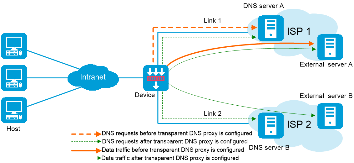
As shown in Figure-1, intranet users of an enterprise can access external servers A and B through link 1 of ISP 1 and link 2 of ISP 2. External servers A and B provide the same services. All DNS requests of intranet users are forwarded to DNS server A, which returns the resolved IP address of external server A to the requesting users. In this way, all traffic of intranet users is forwarded on one link. Link congestion might occur.
The transparent DNS proxy feature can solve this problem by forwarding DNS requests to DNS servers in different ISPs. All traffic from intranet users is evenly distributed on multiple links. This feature can prevent link congestion and ensure service continuity upon a link failure.
Figure-1 Transparent DNS proxy
Transparent DNS proxy workflow
The transparent DNS proxy is implemented by changing the destination IP address of DNS requests.
As shown in Figure-2, if the destination port number of an incoming DNS request is the same as the port number specified for a transparent DNS proxy, the device processes the DNS request as follows:
Finds the DNS server pool associated with the transparent DNS proxy.
Selects a DNS server to service the DNS request according to the scheduling algorithm of the associated DNS server pool.
The IP address of the selected DNS server is used as the destination IP address of the DNS request.
The DNS server resolves the domain name in the DNS request into the IP address of the external server sends a DNS response.
The intranet user accesses the external server according to the resolved IP address in the DNS response.
Figure-2 Transparent DNS proxy workflow

Restrictions and guidelines
The transparent DNS proxy and DNS proxy features are mutually exclusive. Do not configure both features on the device. For more information about DNS proxy, see the help for DNS proxy.
vSystem support information
Support of non-default vSystems for this feature depends on the device model. This feature is available on the Web interface only if it is supported.
Configure transparent DNS proxy
Figure-3 shows the configuration procedure for transparent DNS proxy.
Figure-3 Transparent DNS proxy configuration procedure

Configure health monitoring (optional)
The health monitoring configuration can be used by a DNS server or DNS server pool.
For detailed steps required to configure health monitoring, see the help for load balancing common configuration.
Configure a sticky group (optional)
A sticky group can be used by an IPv4 or IPv6 proxy policy.
For detailed steps required to configure sticky groups, see the help for load balancing common configuration.
Configure a class
A class classifies packets by comparing packets against specific rules. Matching packets are further processed by LB actions.
Procedure
Select Policies > LB Policy > Link Load Balancing > DNS Proxy > Class.
Click Create on the Class page.
Create a class.
Table-1 Class configuration items
Item
Description
Class name
Enter a name for the class, case insensitive.
Match type
Select a match type:
Match any—A packet matches a class if it matches any of the rules in the class.
Match all—A packet matches a class if it matches all rules in the class.
Match rule
A class can contain a maximum of 65535 match rules.
To configure a match rule:
Click Create, and configure the following items on the Create Match Rule page:
Rule ID—Enter a rule ID. Rules are matched in ascending order of rule IDs.
Type—Select a rule type. Options include Source IPv4 address, Source IPv6 address, Destination IPv4 address, Destination IPv6 address, Class, IPv4 ACL, IPv6 ACL, Domain name, User, and Input interface.
IPv4 address—Specify the IPv4 address to match. This parameter appears only if you have selected Source IPv4 address or Destination IPv4 address from the Type list.
Mask length—Specify the mask length for the IPv4 address. This parameter appears only if you have selected Source IPv4 address or Destination IPv4 address from the Type list.
IPv6 address—Specify the IPv6 address to match. This parameter appears only if you have selected Source IPv6 address or Destination IPv6 address from the Type list.
Prefix length—Specify the prefix length for the IPv6 address. This parameter appears only if you have selected Source IPv6 address or Destination IPv6 address from the Type list.
Class—Specify the class to match. This parameter appears only if you have selected Class from the Type list.
IPv4 ACL—Specify the IPv4 ACL to match. You can select an existing ACL or create an ACL. This parameter appears only if you have selected IPv4 ACL from the Type list.
IPv6 ACL—Specify the IPv6 ACL to match. You can select an existing ACL or create an ACL. This parameter appears only if you have selected IPv6 ACL from the Type list.
Domain name—Specify the domain name to match. The domain name is a case-insensitive string of 1 to 253 characters. Each dot-separated part in the domain name can contain a maximum of 63 characters. The domain name can contain letters, digits, hyphens (-), underscores (_), dots (.), and wildcards (asterisks (*) and question marks (?)).The wildcards can substitute any characters except for dots (.). An asterisk (*) can substitute a character string. A question mark (?) can substitute a single character. This parameter appears only if you have selected Domain name from the Type list.
User—Specify the user or user group to match. You can select an existing user or user group or create a user or user group. This parameter appears only if you have selected User from the Type list.
Input interface—Specify the input interface to match. This parameter appears only if you have selected Input interface from the Type list.
Click OK. The new match rule appears in the match rule list.
Description
Enter a description for the class.
Click OK. The new class appears on the Class page.
Configure a link
For detailed steps required to configure links, see the help for load balancing common configuration.
Configure a DNS server
Perform this task to configure an entity on the LB device for processing DNS requests. DNS servers configured on the LB device correspond to DNS servers in ISP networks. A DNS server can belong to multiple DNS server pools. A DNS server pool can contain multiple DNS servers.
Procedure
Select Policies > LB Policy > Link Load Balancing > DNS Proxy > DNS Server.
Click Create on the DNS Server page.
Create a DNS server.
Table-2 DNS server configuration items
Item
Description
DNS server name
Enter a name for the DNS server, case insensitive.
IP address configuration method
Select an IP address configuration method:
Manual.
Automatic—To use this method, an outgoing interface must be specified on the Create Link page.
IPv4 address
Enter an IPv4 address for the DNS server.
The IPv4 address cannot be a loopback address, multicast address, broadcast address, or 0.X.X.X.
IPv6 address
Enter an IPv6 address for the DNS server.
The IPv6 address cannot be a loopback address, multicast address, link-local address, or all-zero address.
Port number
Enter a port number for the DNS server. The value 0 means the port number carried in the packet is used.
VRF
Select a VRF to which the DNS server belongs.
Weight
Enter the weight for the DNS server. A greater value means a higher priority to be selected during weighted round-robin scheduling.
This parameter is available only when you add a DNS server on the DNS Server Pool page.
Priority
Enter a priority for the real server in the server farm. A greater value means a higher priority to be selected.
If the number of real servers with the highest priority is smaller than the configured minimum number, real servers with lower priority are selected to meet the minimum number.
This parameter is available only when you add a DNS server on the DNS Server Pool page.
Probe method
Specify a probe template used by the DNS server to detect health and availability. You can also configure this parameter for all DNS servers in a DNS server pool on the DNS Server Pool page. The configuration performed on the DNS Server page has higher priority over that performed on the DNS Server Pool page.
You can select an existing probe template or create a probe template.
Success criteria
Specify the health monitoring success criteria for the DNS server.
All probes succeed—Health monitoring succeeds only when all the specified health monitoring methods succeed.
At least n probes succeed—Health monitoring succeeds when a minimum of the specified number of health monitoring methods succeed. When the specified number of health monitoring methods is greater than the number of health monitoring methods on the device, health monitoring succeeds if all health monitoring methods succeed.
Link
Specify a link to associate with the DNS server.
You can select an existing link or create a link.
Description
Enter a description for the DNS server.
Click OK. The new DNS server appears on the DNS Server page.
Configure a DNS server pool
By configuring a DNS server pool, you can perform centralized management on DNS servers that have similar functions.
Procedure
Select Policies > LB Policy > Link Load Balancing > DNS Proxy > DNS Server Pool.
Click Create on the DNS Server Pool page.
Create a DNS server pool.
Table-3 DNS server pool configuration items
Item
Description
Pool name
Enter a name for the DNS server pool, case insensitive.
Scheduling algorithm
Select a scheduling algorithm for the DNS server pool.
Bandwidth algorithm—Distributes DNS requests to DNS servers according to the weights and remaining bandwidths of DNS servers. When the remaining bandwidths of two DNS servers are the same, this algorithm is equivalent to the round-robin algorithm. When the weights of two DNS servers are the same, this algorithm always distributes DNS requests to the DNS server that has larger remaining bandwidth.
Random algorithm—Distributes DNS requests to DNS servers randomly.
Weighted round-robin algorithm—Distributes DNS requests to DNS servers in a round-robin manner according to the weights of DNS servers. A DNS server with a greater weight value is assigned more DNS requests.
Maximum bandwidth algorithm—Distributes DNS requests always to an idle DNS server that has the largest remaining bandwidth.
Source IP address hash algorithm—Hashes the source IP address of DNS requests and distributes DNS requests to different DNS servers according to the hash values.
Source IP address and port hash algorithm—Hashes the source IP address and port number of DNS requests and distributes DNS requests to different DNS servers according to the hash values.
Destination IP address hash algorithm—Hashes the destination IP address of DNS requests and distributes DNS requests to different DNS servers according to the hash values.
Priority scheduling
Specify the upper limit and lower limit of DNS servers in a DNS server pool that can be scheduled. By default, all DNS servers with the highest priority in a DNS server pool are scheduled.
If the number of DNS servers with the highest priority is greater than the configured maximum number, the maximum number applies.
If the number of such DNS servers is less than the minimum number, DNS servers with lower priority are selected to meet the minimum number or until no DNS servers are available.
The DNS server priority can be configured on the DNS Server page.
Health monitoring method
Specify a probe template used by the DNS server pool to detect the health and availability of its DNS servers. You can also configure this parameter for a single DNS server on the DNS Server Pool page. The configuration performed on the DNS Server page has higher priority over that performed on the DNS Server Pool page.
You can select an existing probe template or create a probe template.
Success criteria
Specify the health monitoring success criteria for the DNS server pool.
All probes succeed—Health monitoring succeeds only when all the specified health monitoring methods succeed.
At least n probes succeed—Health monitoring succeeds when a minimum of the specified number of health monitoring methods succeed. When the specified number of health monitoring methods is greater than the number of health monitoring methods on the device, health monitoring succeeds if all health monitoring methods succeed.
DNS server list
You can add a DNS server to a DNS server pool in one of the following ways:
Create a DNS server and add it to the DNS server pool.
Click Add, and select Create DNS server.
Configure the parameters for the DNS server (see "Configure a DNS server").
Click OK. The new DNS server appears in the DNS server list.
Select an existing DNS server.
Click Add, and select Select existing DNS server.
Select a DNS server from the list, and configure DNS server parameters (see "Configure a DNS server").
Click OK. The DNS server appears in the DNS server list.
Description
Enter a description for the DNS server pool.
Click OK. The new DNS server pool appears on the DNS Server Pool page.
Configure a proxy policy
A proxy policy associates a class and an action. You can specify an action to take on a class of packets in a proxy policy.
You can specify only one class in a proxy policy. The device matches packets against proxy policies in their configuration order. If a packet matches a class, the device takes the associated action on the packet. If a packet matches no class, the device takes the action associated with the system-defined class named Default on the packet.
Common procedure
Select Policies > LB Policy > Link Load Balancing > DNS Proxy > IPv4/IPv6 Proxy Policy.
On the IPv4/IPv6 Proxy Policy page, configure the common settings.
Table-4 Common configuration items
Item
Description
Status
Status of the transparent DNS proxy:
Available.
Unavailable. Please check the configuration.
Proxy port
Enter a proxy port number. If the destination port number of an incoming DNS request is the same as the proxy port number, the device performs the transparent DNS proxy on the DNS request.
Transparent DNS proxy
Enable or disable the transparent DNS proxy feature.
Link protection
Enable or disable the link protection feature. This feature enables a transparent DNS proxy to select a DNS server based on the link bandwidth ratio. If the bandwidth ratio of a link is exceeded, the DNS server is not selected.
Session extension information synchronization
Enable or disable session extension information synchronization.
Sticky entry synchronization
Enable or disable sticky entry synchronization.
The following configuration changes will cause the device to delete existing sticky entries and generate new ones based on subsequent traffic:
Disable sticky entry synchronization.
Change the sticky entry synchronization type.
Sticky entry synchronization type
Select the sticky entry synchronization type:
Intra-group synchronization—Synchronizes sticky entries to the device in the same failover group.
Global synchronization—Synchronizes sticky entries to devices in all failover groups.
This function is available only when sticky entry synchronization is enabled.
Procedure for configuring an IPv4/IPv6 proxy policy
Select Policies > Link Load Balancing > DNS Proxy > IPv4/IPv6 Proxy Policy.
Click Create on the IPv4/IPv6 Proxy Policy page.
Create an IPv4/IPv6 proxy policy.
Table-5 IPv4/IPv6 proxy policy configuration items
Item
Description
Class
Select an existing class or create a class.
Forwarding action
Select a forwarding action.
Load balance
Discard
Forward
Skip the transparent DNS proxy
If the IPv4/IPv6 proxy policy is used by a SIP virtual server, the Forward option does not take effect.
ToS
Enter the ToS field value in IP packets sent to the DNS server.
DNS server pool
Select an existing DNS server pool or create a DNS server pool.
Sticky group
Select an existing sticky group or create a sticky group.
Only address-port sticky groups are supported.
Fallback action
Specify that the next rule is matched when a failure to find a DNS server occurs.
Busy action
Specify that the next rule is matched when all DNS servers are busy.
Insert before
Specify an existing proxy policy before which the new policy is inserted.
Click OK. The new proxy policy appears on the IPv4/IPv6 Proxy Policy page.