- Table of Contents
-
- 06-Layer 3 - IP Routing Configuration Guides
- 00-Preface
- 01-Basic IP routing configuration
- 02-Static routing configuration
- 03-RIP configuration
- 04-OSPF configuration
- 05-IS-IS configuration
- 06-BGP configuration
- 07-Policy-based routing configuration
- 08-IPv6 static routing configuration
- 09-RIPng configuration
- 10-OSPFv3 configuration
- 11-IPv6 policy-based routing configuration
- 12-Routing policy configuration
- 13-DCN configuration
- 14-Dual-stack PBR configuration
- Related Documents
-
| Title | Size | Download |
|---|---|---|
| 08-IPv6 static routing configuration | 208.72 KB |
Configuring IPv6 static routing
Configuring an IPv6 static route
Configuring IPv6 floating static routes
Configuring BFD for IPv6 static routes
Configuration restrictions and guidelines
Configuring BFD control packet mode
Configuring BFD echo packet mode
Enabling periodic sending of ND requests to the next hops of IPv6 static routes
Displaying and maintaining IPv6 static routes
IPv6 static routing configuration examples
Basic IPv6 static route configuration example
BFD for IPv6 static routes configuration example (direct next hop)
BFD for IPv6 static routes configuration example (indirect next hop)
Configuring an IPv6 default route
Configuring IPv6 static routing
Static routes are manually configured and cannot adapt to network topology changes. If a fault or a topological change occurs in the network, the network administrator must modify the static routes manually. IPv6 static routing works well in a simple IPv6 network.
Configuring an IPv6 static route
Before you configure an IPv6 static route, complete the following tasks:
· Configure parameters for the related interfaces.
· Configure link layer attributes for the related interfaces.
· Make sure the neighboring nodes can reach each other.
If you configure only VPN instance settings without specifying a next hop for an IPv6 static route, you must also configure service loopback group settings for the IPv6 static route to take effect.
To configure service loopback group settings for an IPv6 static route:
1. Create a service loopback group of the inter-VPN forwarding service type.
2. Add any Layer 2 Ethernet interface to the service loopback group. To ensure that the IPv6 static route can correctly guide traffic forwarding, do not add the Layer 2 Ethernet interfaces on the following cards to the service loopback group:
¡ SF interface modules.
¡ EC interface modules.
¡ SA interface modules.
¡ SC interface modules.
For more information about service loopback group configuration, see Layer 2—LAN Switching Configuration Guide.
To configure an IPv6 static route:
|
Step |
Command |
Remarks |
|
1. Enter system view. |
system-view |
N/A |
|
2. Configure an IPv6 static route. |
· Method 1: · Method 2: |
By default, no IPv6 static route is configured. The recursive-lookup host-route and recursive-lookup keywords are mutually exclusive. If you specify a destination VPN instance without specifying a next hop address, the destination VPN instance cannot be the same as the source VPN instance. |
|
3. (Optional.) Set the default preference for IPv6 static routes. |
ipv6 route-static default-preference default-preference |
The default setting is 60. |
|
4. (Optional.) Delete all IPv6 static routes, including the default route. |
delete ipv6 [ vpn-instance vpn-instance-name ] static-routes all |
The undo ipv6 route-static command deletes one IPv6 static route.
Deleting all IPv6 static routes might cause network connectivity failure and packet forwarding failure. Perform this operation with caution. |
Configuring IPv6 floating static routes
Perform this task to configure route backup to improve network reliability.
When an IPv6 static or dynamic route to a destination address already exists on the device, you configure another IPv6 static route with a lower priority as the backup route to improve the network reliability. This backup IPv6 static route is called an IPv6 floating static route and is activated only when the primary route fails. After the primary route recovers from failure, the IPv6 floating static route becomes inactive and data forwarding switches back to the primary route.
An IPv6 floating static route can be configured in either of the following ways
· Configure different priorities for multiple IPv6 static routes to the same destination address. The route with the lower priority automatically becomes the IPv6 floating static route.
· When an IPv6 route to a destination address already exists on the device, configure an IPv6 static route with a lower priority to the same destination address.
When you configure an IPv6 floating static route, the priority value of the route must be larger than then priority value of the primary route. For more information, see "Configuring an IPv6 static route."
Configuring BFD for IPv6 static routes
Overview
BFD provides a general purpose, standard, and medium- and protocol-independent fast failure detection mechanism. It can uniformly and quickly detect the failures of the bidirectional forwarding paths between two routers for protocols, such as routing protocols and MPLS. For more information about BFD, see High Availability Configuration Guide.
Configuration restrictions and guidelines
When you configure BFD for IPv6 static routes, follow these restrictions and guidelines:
· If you specify a source IPv6 address for BFD packets on the local device, you must specify that IPv6 address as the next hop IPv6 address on the peer device.
· If you specify a non-P2P output interface and a direct next hop, specify the bfd-source ipv6-address option as a best practice. Make sure the source IPv6 address of BFD packets meets the following requirements:
¡ The address is the same as the IPv6 address of the output interface.
¡ The address is on the same network segment as the next hop IPv6 address of the same type.
For example, if the next hop IPv6 address is a link-local address, the source IPv6 address of BFD packets must also be a link-local address.
· Enabling BFD for a flapping route could worsen the situation.
Configuring BFD control packet mode
This mode uses BFD control packets to detect the status of a link bidirectionally at a millisecond level.
BFD control packet mode can be applied to IPv6 static routes with a direct next hop or with an indirect next hop.
If you configure BFD control packet mode at the local end, you must also configure this mode at the peer end.
To configure BFD control packet mode for an IPv6 static route (direct next hop):
|
Step |
Command |
Remarks |
|
1. Enter system view. |
system-view |
N/A |
|
2. Configure BFD control packet mode for an IPv6 static route. |
ipv6 route-static [ vpn-instance s-vpn-instance-name ] ipv6-address prefix-length interface-type interface-number next-hop-address bfd control-packet [ bfd-source ipv6-address ] [ preference preference ] [ tag tag-value ] [ description text ] |
By default, BFD control packet mode for an IPv6 static route is not configured. |
To configure BFD control packet mode for an IPv6 static route (indirect next hop):
|
Step |
Command |
Remarks |
|
1. Enter system view. |
system-view |
N/A |
|
2. Configure BFD control packet mode for an IPv6 static route. |
ipv6 route-static [ vpn-instance s-vpn-instance-name ] ipv6-address prefix-length [ vpn-instance d-vpn-instance-name ] { next-hop-address [ recursive-lookup host-route ] bfd control-packet bfd-source ipv6-address } [ preference preference ] [ tag tag-value ] [ description text ] |
By default, BFD control packet mode for an IPv6 static route is not configured. |
Configuring BFD echo packet mode
With BFD echo packet mode enabled for a static route, the output interface sends BFD echo packets to the destination device, which loops the packets back to test the link reachability.
Configuration restrictions and guidelines
You do not need to configure BFD echo packet mode at the peer end.
Do not use BFD for a static route with the output interface in spoofing state.
Configuration procedure
To configure BFD echo packet mode for an IPv6 static route:
|
Step |
Command |
Remarks |
|
1. Enter system view. |
system-view |
N/A |
|
2. Configure the source address of echo packets. |
bfd echo-source-ipv6 ipv6-address |
By default, the source address of echo packets is not configured. The source address of echo packets must be a global unicast address. As a best practice to avoid network congestion caused by excessive ICMPv6 redirect packets from the peer, use this command to specify a source IPv6 address that is not on the subnet of any interfaces on the device. For more information about this command, see High Availability Command Reference. |
|
3. Configure BFD echo packet mode for an IPv6 static route. |
ipv6 route-static [ vpn-instance s-vpn-instance-name ] ipv6-address prefix-length interface-type interface-number next-hop-address bfd echo-packet [ bfd-source ipv6-address ] [ preference preference ] [ tag tag-value ] [ description text ] |
By default, BFD echo packet mode for an IPv6 static route is not configured. The next hop IPv6 address must be a global unicast address. |
Enabling periodic sending of ND requests to the next hops of IPv6 static routes
As a best practice, use this feature when the following types of IPv6 static routes exist on the device:
· IPv6 static routes that recurse to host routes, which include the following IPv6 static routes:
¡ IPv6 static routes with the recursive-lookup host-route keywords specified to recurse only to host routes.
¡ IPv6 static routes that recurse to host routes according to routing policies (configured by using the protocol nexthop recursive-lookup command).
The device might delete the ND entry for the next hop host address of an IPv6 static route after that entry ages out because the device cannot update that entry in time. As a result, the device does not have the host route of the directly connected device in the IPv6 routing table for that IPv6 static route. In this case, route recursion fails and that IPv6 static route cannot be activated.
· IPv6 static routes with the track-nd keyword specified to associate their next hops with the ND entries for these next hops.
The device might delete the ND entry for the next hop address of an IPv6 static route after that entry ages out because the device cannot update that entry in time. As a result, that IPv6 static route cannot be activated.
For IPv6 static routes that recurse to host routes, the ipv6 route-static nd-request command enables the device to periodically send ND requests to the next hops of the IPv6 static routes that meet the following requirements:
· The IPv6 static routes have no output interfaces specified.
· The IPv6 static routes fail the next-hop recursion.
When the device receives an ND response from the next hop host of an IPv6 static route, it automatically performs the following operations:
1. Adds the host route to the routing table.
2. Activates the IPv6 static route that recurses to the host route.
3. Stops sending ND requests to the host.
For IPv6 static routes with the track-nd keyword specified, the ipv6 route-static nd-request command enables the device to periodically send ND requests to the next hops of the IPv6 static routes associated with next hop ND entries. When the device receives an ND response from the next hop of an IPv6 static route, it automatically activates that IPv6 static route and stops sending ND requests to the next hop of that IPv6 static route.
To enable periodic sending of ND requests to the next hops of IPv6 static routes:
|
Step |
Command |
Remarks |
|
1. Enter system view. |
system-view |
N/A |
|
2. Enable periodic sending of ND requests to the next hops of IPv6 static routes. |
ipv6 route-static nd-request [ interval interval ] |
By default, periodic sending of ND requests to the next hops of IPv6 static routes is disabled. |
Displaying and maintaining IPv6 static routes
Execute display commands in any view.
|
Task |
Command |
|
Display IPv6 static route information. |
display ipv6 routing-table protocol static [ inactive | verbose ] |
|
Display IPv6 static route next hop information. |
display ipv6 route-static nib [ nib-id ] [ verbose ] |
|
Display IPv6 static routing table information. |
display ipv6 route-static routing-table [ vpn-instance vpn-instance-name ] [ ipv6-address prefix-length ] |
IPv6 static routing configuration examples
Basic IPv6 static route configuration example
Network requirements
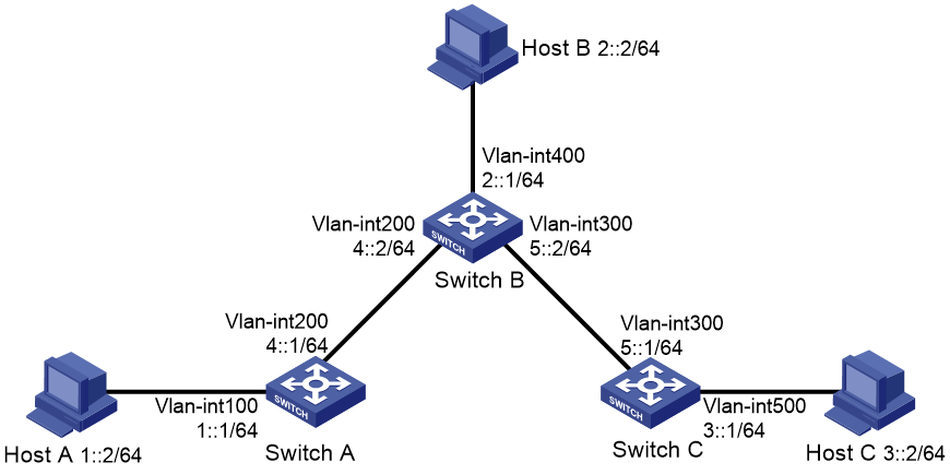
As shown in Figure 1, configure IPv6 static routes so that hosts can reach one another.
Configuration procedure
1. Configure the IPv6 addresses for all VLAN interfaces. (Details not shown.)
2. Configure IPv6 static routes:
# Configure a default IPv6 static route on Switch A.
<SwitchA> system-view
[SwitchA] ipv6 route-static :: 0 4::2
# Configure two IPv6 static routes on Switch B.
<SwitchB> system-view
[SwitchB] ipv6 route-static 1:: 64 4::1
[SwitchB] ipv6 route-static 3:: 64 5::1
# Configure a default IPv6 static route on Switch C.
<SwitchC> system-view
[SwitchC] ipv6 route-static :: 0 5::2
3. Configure the IPv6 addresses for all the hosts and configure the default gateway of Host A, Host B, and Host C as 1::1, 2::1, and 3::1.
Verifying the configuration
# Display the IPv6 static route information on Switch A.
[SwitchA] display ipv6 routing-table protocol static
Summary count : 1
Static Routing table status : <Active>
Summary count : 1
Destination: ::/0 Protocol : Static
NextHop : 4::2 Preference: 60
Interface : Vlan200 Cost : 0
Static Routing table status : <Inactive>
Summary count : 0
# Display the IPv6 static route information on Switch B.
[SwitchB] display ipv6 routing-table protocol static
Summary count : 2
Static Routing table status : <Active>
Summary count : 2
Destination: 1::/64 Protocol : Static
NextHop : 4::1 Preference: 60
Interface : Vlan200 Cost : 0
Destination: 3::/64 Protocol : Static
NextHop : 5::1 Preference: 60
Interface : Vlan300 Cost : 0
Static Routing table status : <Inactive>
Summary count : 0
# Use the ping command to test the reachability.
[SwitchA] ping ipv6 3::1
Ping6(56 data bytes) 4::1 --> 3::1, press CTRL+C to break
56 bytes from 3::1, icmp_seq=0 hlim=62 time=0.700 ms
56 bytes from 3::1, icmp_seq=1 hlim=62 time=0.351 ms
56 bytes from 3::1, icmp_seq=2 hlim=62 time=0.338 ms
56 bytes from 3::1, icmp_seq=3 hlim=62 time=0.373 ms
56 bytes from 3::1, icmp_seq=4 hlim=62 time=0.316 ms
--- Ping6 statistics for 3::1 ---
5 packet(s) transmitted, 5 packet(s) received, 0.0% packet loss
round-trip min/avg/max/std-dev = 0.316/0.416/0.700/0.143 ms
BFD for IPv6 static routes configuration example (direct next hop)
Network requirements
As shown in Figure 2:
· Configure an IPv6 static route to subnet 120::/64 on Switch A.
· Configure an IPv6 static route to subnet 121::/64 on Switch B.
· Enable BFD for both routes.
· Configure an IPv6 static route to subnet 120::/64 and an IPv6 static route to subnet 121::/64 on Switch C.
When the link between Switch A and Switch B through the Layer 2 switch fails, BFD can detect the failure immediately, and Switch A and Switch B can communicate through Switch C.
Figure 2 Network diagram
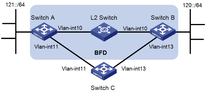
Table 1 Interface and IP address assignment
|
Device |
Interface |
IPv6 address |
|
Switch A |
Vlan-int10 |
12::1/64 |
|
Switch A |
Vlan-int11 |
10::102/64 |
|
Switch B |
Vlan-int10 |
12::2/64 |
|
Switch B |
Vlan-int13 |
13::1/64 |
|
Switch C |
Vlan-int11 |
10::100/64 |
|
Switch C |
Vlan-int13 |
13::2/64 |
Configuration procedure
1. Configure IPv6 addresses for interfaces. (Details not shown.)
2. Configure IPv6 static routes and BFD:
# Configure IPv6 static routes on Switch A and enable BFD control packet mode for the static route that traverses the Layer 2 switch.
<SwitchA> system-view
[SwitchA] interface vlan-interface 10
[SwitchA-vlan-interface10] bfd min-transmit-interval 500
[SwitchA-vlan-interface10] bfd min-receive-interval 500
[SwitchA-vlan-interface10] bfd detect-multiplier 9
[SwitchA-vlan-interface10] quit
[SwitchA] ipv6 route-static 120:: 64 vlan-interface 10 12::2 bfd control-packet
[SwitchA] ipv6 route-static 120:: 64 10::100 preference 65
[SwitchA] quit
# Configure IPv6 static routes on Switch B and enable BFD control packet mode for the static route that traverses the Layer 2 switch.
<SwitchB> system-view
[SwitchB] interface vlan-interface 10
[SwitchB-vlan-interface10] bfd min-transmit-interval 500
[SwitchB-vlan-interface10] bfd min-receive-interval 500
[SwitchB-vlan-interface10] bfd detect-multiplier 9
[SwitchB-vlan-interface10] quit
[SwitchB] ipv6 route-static 121:: 64 vlan-interface 10 12::1 bfd control-packet
[SwitchB] ipv6 route-static 121:: 64 vlan-interface 13 13::2 preference 65
[SwitchB] quit
# Configure IPv6 static routes on Switch C.
<SwitchC> system-view
[SwitchC] ipv6 route-static 120:: 64 13::1
[SwitchC] ipv6 route-static 121:: 64 10::102
Verifying the configuration
# Display the BFD sessions on Switch A.
<SwitchA> display bfd session
Total sessions: 1 Up sessions: 1 Init mode: Active
IPv6 session working in control packet mode:
Local Discr: 513 Remote Discr: 33
Source IP: 12::1
Destination IP: 12::2
Session State: Up Interface: Vlan10
Hold Time: 2012ms
The output shows that the BFD session has been created.
# Display IPv6 static routes on Switch A.
<SwitchA> display ipv6 routing-table protocol static
Summary count : 1
Static Routing table status : <Active>
Summary count : 1
Destination: 120::/64 Protocol : Static
NextHop : 12::2 Preference: 60
Interface : Vlan10 Cost : 0
Direct Routing table status : <Inactive>
Summary count : 0
The output shows that Switch A communicates with Switch B through VLAN-interface 10. The link over VLAN-interface 10 fails.
# Display IPv6 static routes on Switch A again.
<SwitchA> display ipv6 routing-table protocol static
Summary count : 1
Static Routing table status : <Active>
Summary count : 1
Destination: 120::/64 Protocol : Static
NextHop : 10::100 Preference: 65
Interface : Vlan11 Cost : 0
Static Routing table status : < Inactive>
Summary count : 0
The output shows that Switch A communicates with Switch B through VLAN-interface 11.
BFD for IPv6 static routes configuration example (indirect next hop)
Network requirements
As shown in Figure 3:
· Switch A has a route to interface Loopback 1 (2::9/128) on Switch B, and the output interface is VLAN-interface 10.
· Switch B has a route to interface Loopback 1 (1::9/128) on Switch A, and the output interface is VLAN-interface 12.
· Switch D has a route to 1::9/128, and the output interface is VLAN-interface 10. It also has a route to 2::9/128, and the output interface is VLAN-interface 12.
Configure the following:
· Configure an IPv6 static route to subnet 120::/64 on Switch A.
· Configure an IPv6 static route to subnet 121::/64 on Switch B.
· Enable BFD for both routes.
· Configure an IPv6 static route to subnet 120::/64 and an IPv6 static route to subnet 121::/64 on both Switch C and Switch D.
When the link between Switch A and Switch B through Switch D fails, BFD can detect the failure immediately and Switch A and Switch B can communicate through Switch C.
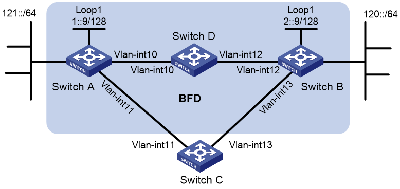
Table 2 Interface and IP address assignment
|
Device |
Interface |
IPv6 address |
|
Switch A |
Vlan-int10 |
12::1/64 |
|
Switch A |
Vlan-int11 |
10::102/64 |
|
Switch A |
Loop1 |
1::9/128 |
|
Switch B |
Vlan-int12 |
11::2/64 |
|
Switch B |
Vlan-int13 |
13::1/64 |
|
Switch B |
Loop1 |
2::9/128 |
|
Switch C |
Vlan-int11 |
10::100/64 |
|
Switch C |
Vlan-int13 |
13::2/64 |
|
Switch D |
Vlan-int10 |
12::2/64 |
|
Switch D |
Vlan-int12 |
11::1/64 |
Configuration procedure
1. Configure IPv6 addresses for interfaces. (Details not shown.)
2. Configure IPv6 static routes and BFD:
# Configure IPv6 static routes on Switch A and enable BFD control packet mode for the IPv6 static route that traverses Switch D.
<SwitchA> system-view
[SwitchA] bfd multi-hop min-transmit-interval 500
[SwitchA] bfd multi-hop min-receive-interval 500
[SwitchA] bfd multi-hop detect-multiplier 9
[SwitchA] ipv6 route-static 120:: 64 2::9 bfd control-packet bfd-source 1::9
[SwitchA] ipv6 route-static 120:: 64 10::100 preference 65
[SwitchA] ipv6 route-static 2::9 128 12::2
[SwitchA] quit
# Configure IPv6 static routes on Switch B and enable BFD control packet mode for the static route that traverses Switch D.
<SwitchB> system-view
[SwitchB] bfd multi-hop min-transmit-interval 500
[SwitchB] bfd multi-hop min-receive-interval 500
[SwitchB] bfd multi-hop detect-multiplier 9
[SwitchB] ipv6 route-static 121:: 64 1::9 bfd control-packet bfd-source 2::9
[SwitchB] ipv6 route-static 121:: 64 13::2 preference 65
[SwitchB] ipv6 route-static 1::9 128 11::1
[SwitchB] quit
# Configure IPv6 static routes on Switch C.
<SwitchC> system-view
[SwitchC] ipv6 route-static 120:: 64 13::1
[SwitchC] ipv6 route-static 121:: 64 10::102
# Configure IPv6 static routes on Switch D.
<SwitchD> system-view
[SwitchD] ipv6 route-static 120:: 64 11::2
[SwitchD] ipv6 route-static 121:: 64 12::1
[SwitchD] ipv6 route-static 2::9 128 11::2
[SwitchD] ipv6 route-static 1::9 128 12::1
Verifying the configuration
# Display the BFD sessions on Switch A.
<SwitchA> display bfd session
Total sessions: 1 Up sessions: 1 Init mode: Active
IPv6 session working in control packet mode:
Local Discr: 513 Remote Discr: 33
Source IP: 1::9
Destination IP: 2::9
Session State: Up Interface: N/A
Hold Time: 2012ms
The output shows that the BFD session has been created.
# Display the IPv6 static routes on Switch A.
<SwitchA> display ipv6 routing-table protocol static
Summary count : 1
Static Routing table status : <Active>
Summary count : 1
Destination: 120::/64 Protocol : Static
NextHop : 2::9 Preference: 60
Interface : Vlan10 Cost : 0
Static Routing table status : <Inactive>
Summary count : 0
The output shows that Switch A communicates Switch B through VLAN-interface 10. The link over VLAN-interface 10 fails.
# Display IPv6 static routes on Switch A again.
<SwitchA> display ipv6 routing-table protocol static
Summary count : 1
Static Routing table status : <Active>
Summary count : 1
Destination: 120::/64 Protocol : Static
NextHop : 10::100 Preference: 65
Interface : Vlan11 Cost : 0
Static Routing table status : <Inactive>
Summary count : 0
The output shows that Switch A communicates with Switch B through VLAN-interface 11.
Configuring an IPv6 default route
A default IPv6 route is used to forward packets that match no entry in the routing table.
A default IPv6 route can be configured in either of the following ways:
· The network administrator can configure a default route with a destination prefix of ::/0. For more information, see "Configuring IPv6 static routing."
· Some dynamic routing protocols, such as OSPFv3, IPv6 IS-IS, and RIPng, can generate a default IPv6 route. For example, an upstream router running OSPFv3 can generate a default IPv6 route and advertise it to other routers. These routers install the default IPv6 route with the next hop being the upstream router. For more information, see the respective chapters on those routing protocols in this configuration guide.
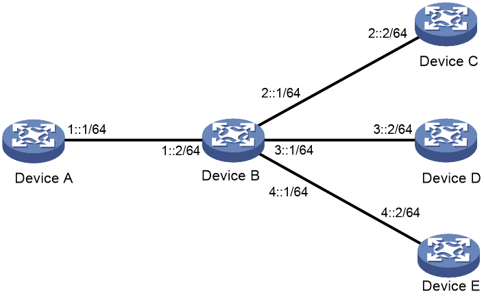
As shown in Figure 4, Device B is the next hop for packets from Device A to Device C, Device D, and Device E. You can configure a default route on Device A to replace the three IPv6 static routes from Device A to Device C, Device D, and Device E, respectively.
The next hop address, destination address, and subnet mask of the IPv6 default route configured on Device A are 1::2, ::, and 0, respectively.
Figure 4 Configuring a default route