| Title | Size | Downloads |
|---|---|---|
| H3C ANT-2003CM antenna installation guide-5PW100-book.pdf | 392.67 KB |
- Table of Contents
- Related Documents
-
- H3C ANT-2015P patch antenna installation guide-5PW100
- H3C ANT-2011P patch antenna installation guide-5PW100
- H3C ANT-2009Y Yagi antenna installation guide-5PW100
- H3C ANT-2005W antenna installtion guide-5PW100
- H3C ANT-5016P-M2 Patch Antenna Installation Guide-5W100
- H3C ANT-2513P-M2 Patch Antenna Installation Guide-5W100
Contents
H3C ANT-2003CM antenna installation guide
Tools and accessories required
Mounting the antenna on a ceiling
Mounting the antenna on a wall
Technical specifications
The ANT-2003CM antenna is designed for use in indoor environments. It is connected to the 2.4-GHz antenna port on an H3C indoor AP through an SMA-type connector.
Figure 1 Antenna view
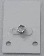
Table 1 Technical specifications
|
Antenna type |
ANT-2003CM |
|
Operating frequency range |
2400 MHz to 2500 MHz |
|
Bandwidth |
100 MHz |
|
Peak gain |
3 dBi |
|
Front to Back Ratio (dB) |
≥ NA |
|
Horizontal beamwidth |
360 degrees |
|
Vertical beamwidth |
60 to 80 degrees |
|
Voltage standing wave ratio (VSWR) |
≤1.5 |
|
Impedance |
50 Ω |
|
Polarization type |
Vertical |
|
Max. power |
10 W |
|
Connector |
SMA-Female |
|
Third Order Intermodulation (dBm) |
N/A |
|
Lightning protection |
DC grounding |
|
Dimensions |
44 × 28 × 2 mm (1.73 × 1.10 × 0.08 in) |
|
Weight |
0.006 kg (0.01 lb) |
|
Operating temperature |
–40°C to +60°C (–40°F to +140°F) |
|
Mast diameter (mm) |
N/A |
|
Wind resistance (km/h) |
N/A |
|
Installation |
Ceiling mounting or wall mounting |
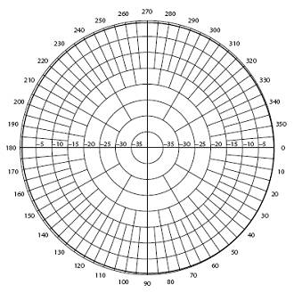
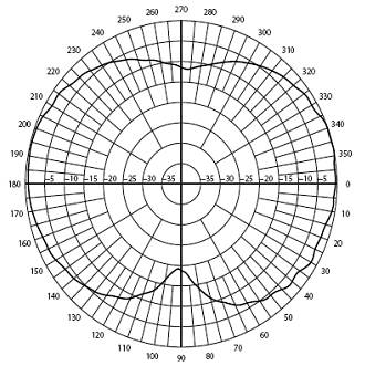
Figure 2 and Figure 3 show the horizontal and vertical radiation patterns.
Safety precautions
|
|
WARNING! · Installing antennas is dangerous. For your safety, follow the installation directions. · Keep the antenna away from power source, street lamps, distribution box, or other places that may cause electrical shock. · Do not touch any power lines for your safety. |
· Keep safety in mind when you select your installation site. Keep the antenna away from electric power lines and other lines.
· Do not work alone when you install the antenna.
· If you need to raise the mast, work with other people to avoid bodily injury.
· Do not use a metal ladder. Do not work on a wet or windy day. Dress properly, for example, shoes with rubber soles. Wear rubber gloves.
· If the antenna, antenna cable, or any other installation accessory drops, get away from it to avoid bodily injury.
· If an accident, for example, electrical shock, occurs with the power lines, immediately call for qualified emergency help.
Installation guidelines
Keep the antenna away from metal obstructions such as heating and air-conditioning ducts. Typically, the higher an antenna is above the ground, the better it performs. If possible, use a cable as short as possible to connect the antenna and AP.
Mounting the antenna
You can mount the ANT-2003CM antenna on a ceiling or on a wall. The installation accessories are provided (installation tools are user supplied). If you intend to mount your antenna on another surface, you must provide the appropriate installation accessories.
Tools and accessories required
· Accessories provided with the antenna:
? Two wall anchors
? Two screws
? Two curved spring washers
? One cable
? Two bolts
· User-supplied tools:
? One Phillips screwdriver
? One electric drill and associated drill bits
? One pencil
Mounting the antenna on a ceiling
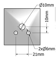
1. Use a pencil to mark the screw positions on the ceiling where you want to mount the antenna and then drill three holes in the ceiling. See Figure 4.
Figure 4 Drilling holes in the ceiling
2. Thread the antenna cable connector and bolts through the three holes you drilled in step 1 until the base of the antenna is flush with the ceiling. See Figure 5.
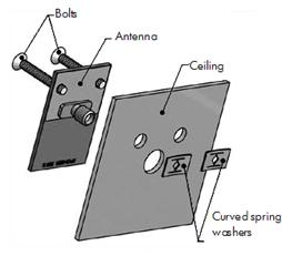
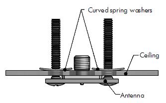
3. From above the ceiling, thread the supplied spring washers through the bolts and fasten them until the antenna is secured in place. See Figure 6.
Mounting the antenna on a wall
1. Use a pencil to mark screw positions on the wall where you want to mount the antenna and then drill three holes in the wall. See Figure 7.
Figure 7 Drilling holes in the wall
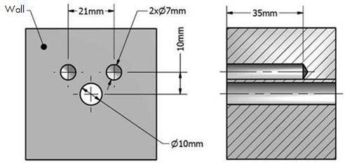
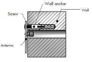
2. Thread the wall anchors through the two 7 mm (0.28 in) holes in the wall and thread the screws through the corresponding holes in the antenna. See Figure 8.
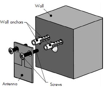
3. Insert the expansion screws into the two wall anchors and fasten them until the antenna is secured in place. See Figure 9.
Recommended cable
H3C recommends that you use a high-quality, low-loss cable with the antenna. Coaxial cable loses efficiency as the frequency increases, causing signal loss. Keep the cable as short as possible because cable length also causes signal loss (the longer the run, the greater the loss).
