H3C Workspace Cloud Desktop Dual Network Isolation Configuration Guide(Office Scenario)-E1013 Series-5W100-book.pdf  (1.74 MB)
- Released At: 08-10-2023
- Page Views:
- Downloads:
- Table of Contents
- Related Documents
-
|
H3C Workspace Cloud Desktop |
Dual Network Isolation Configuration Guide (Office Scenario) |
|
|
Document version: 5W100-20230815
Copyright © 2023 New H3C Technologies Co., Ltd. All rights reserved.
No part of this manual may be reproduced or transmitted in any form or by any means without prior written consent of New H3C Technologies Co., Ltd.
Except for the trademarks of New H3C Technologies Co., Ltd., any trademarks that may be mentioned in this document are the property of their respective owners.
The information in this document is subject to change without notice.
Contents
Intranet and extranet data physical isolation· 2
Simple switchover between internal and external networks· 2
Two Space Consoles available for one endpoint 2
Restrictions and guidelines· 2
Configuring dual network isolation in the DHCP IP address allocation scenario· 3
Configuring dual network isolation in the static IP address allocation scenario· 7
Configuring dual network isolation in the DHCP and static IP address allocation scenario· 14
Verifying the configuration· 20
Overview
Highly confidential institutions or companies typically set up internal LANs where employees can only work and access company resources. When deploying cloud desktops, these organizations require a reliable method to ensure complete isolation between the internal LANs and external networks. This approach satisfies both the need for users to work within the internal LANs and to access Internet resources.
H3C Workspace cloud desktop dual network isolation uses network switchers to implement network isolation and switchover, as shown in Figure 1.
Figure 1 Dual network isolation
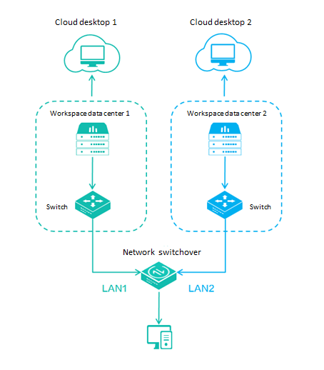
| NOTE: With a network switcher integrated, the C113S endpoint has 2 ports and a network switcher button. The operational principles and usage of the two ports are the same as those of an external network switcher. |
Advantages
Intranet and extranet data physical isolation
An endpoint connects to the network switcher via only one port, and the two ports on the network switcher are physically isolated, with no impact between the two networks. The endpoint can only use a cloud desktop on a server within a single network in one session.
Simple switchover between internal and external networks
When users need to switch between the internal and external networks, they simply need to press the switcher button on the network switcher. The client will automatically switch to the corresponding network management platform server.
Two Space Consoles available for one endpoint
With the dual network isolation feature, two Space Consoles can be used on one endpoint and switched by a switcher. In scenarios where multiple management platforms need to be deployed, this feature can effectively save the cost and space of user-side devices (endpoints, monitors, keyboards, and mice), and reduce the difficulty of deployment.
Usage guidelines
This guide uses E1013P11 as an example to introduce how to use dual network isolation. The configuration procedure might differ by software version.
Prerequisites
Before configuring the dual network isolation feature, verify that the following prerequisites are met:
· H3C Space Consoles in both networks have been installed and deployed.
· User accounts have been created, cloud desktops have been deployed, and users have been authorized to use the cloud desktops in both H3C Space Consoles.
· The endpoints and network switcher have been deployed according to the network plan. For non-C113S endpoints, the network switcher ports need to be directly connected to the endpoint ports.
Restrictions and guidelines
When you use the dual network isolation feature, follow these restrictions and guidelines:
· Enable the spanning tree edge port feature on the edge ports where an endpoint is connected to the switch. This will enable quick port migration and expedite network recovery.
· The dual network isolation feature is only supported by VDI endpoints.
Procedure
Based on the endpoint IP address allocation method in dual networks (static IP address or DHCP), dual network isolation supports the following scenarios:
· Endpoints use DHCP to obtain IP addresses in both networks, LAN1 and LAN2 in Figure 1 for example.
· Endpoints use static IP addresses in both networks.
· Endpoints use DHCP-allocated IP addresses in one network (LAN1) and static IP addresses in the other network (LAN2).
This document uses an endpoint running the SpaceOS operating system as an example. The configuration process is the same for endpoints running the Windows operating system.
Configuring dual network isolation in the DHCP IP address allocation scenario
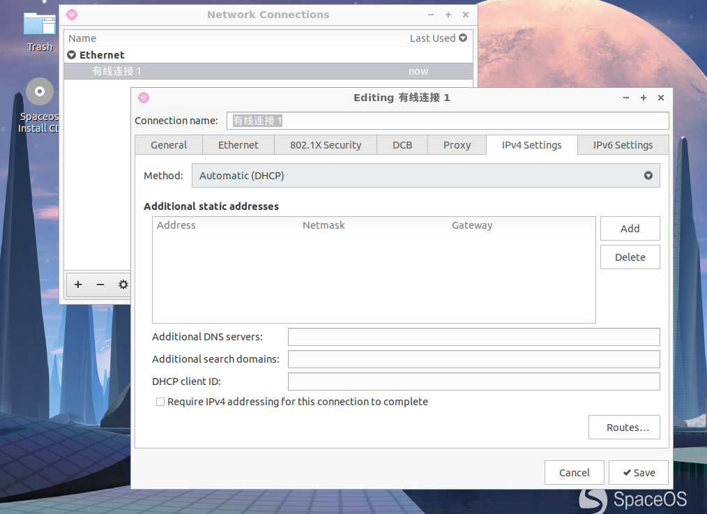
1. Switch the network switcher to LAN1. On the endpoint, click the menu button in the bottom left corner and then select Preferences > Network Connections. Double-click the wired connection, click the IPv4 Settings tab, and then set Method to Automatic (DHCP).
Figure 2 Enabling DHCP for the endpoint local network connection

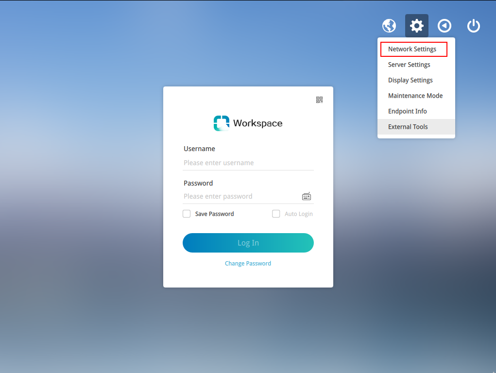
2. Launch the Workspace client, click the configure icon in the top right corner, and then select Network Settings.
Figure 3 Selecting the Network Settings option
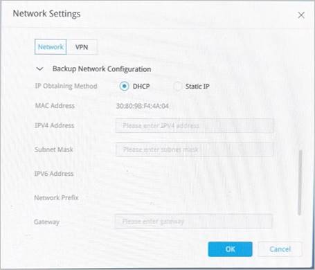
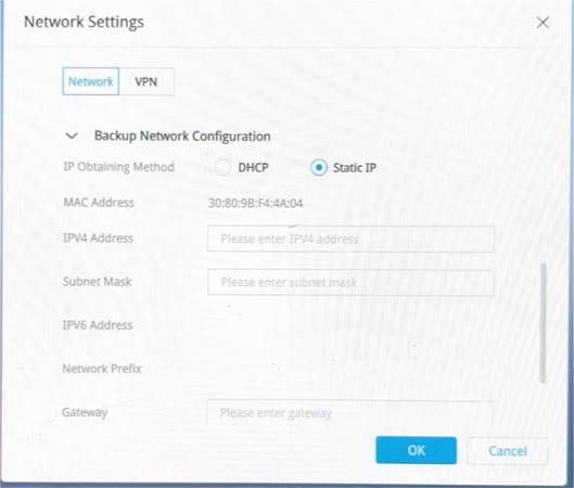
3. Click the Network tab, set the IP address allocation method to DHCP for both the primary and backup networks, and then click OK.
| NOTE: The primary network is LAN1, and the secondary network is LAN2. |
Figure 4 DHCP configuration for primary network LAN1
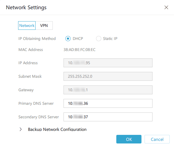
Figure 5 DHCP configuration for backup network LAN2
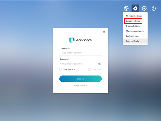
4. On the Workspace client, click the configure icon in the top right corner, and then select Server Settings.
Figure 6 Selecting the Server Settings option
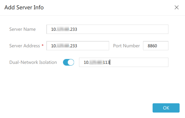
5. Click Add Server to add a server, or click the ![]() icon to edit an existing server. In the server configuration dialog box, enable dual network isolation, configure the IP addresses of two servers, use the default port number 8860, and then click OK.
icon to edit an existing server. In the server configuration dialog box, enable dual network isolation, configure the IP addresses of two servers, use the default port number 8860, and then click OK.
Figure 7 Adding or editing a server

Figure 8 Configuring the IP addresses of two servers
6. Select the server with dual network isolation enabled, and then click OK. Then, proceed to "Verifying the configuration."
Figure 9 Selecting the server with dual network isolation enabled

Configuring dual network isolation in the static IP address allocation scenario
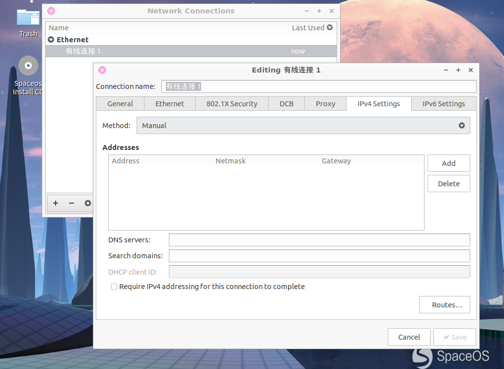
1. Switch the network switcher to LAN1. On the endpoint, click the menu button in the bottom left corner and then select Preferences > Network Connections. Double-click the wired connection, click the IPv4 Settings tab, set Method to Manual, and then enter a static IP address for the network connection.
| NOTE: · This step establishes network connectivity between the client and the management platform and allows for static IP address allocation in the primary and backup networks on the client. · After you configure the primary and backup networks and dual network isolation, change the IP address allocation method of the endpoint to DHCP, as shown in step 8. This allows the client to issue the primary and backup network information to the endpoint's local connection. |
Figure 10 Configuring a static IP address for the endpoint local network connection
2. Launch the Workspace client, click the configure icon in the top right corner, and then select Network Settings.
Figure 11 Selecting the Network Settings option

3. Click the Network tab, set the IP address allocation method to static for both the primary and backup networks, configure static IP addresses for the networks, and then click OK.
| NOTE: The primary network is LAN1, and the secondary network is LAN2. |
Figure 12 Static IP address configuration for primary network LAN1
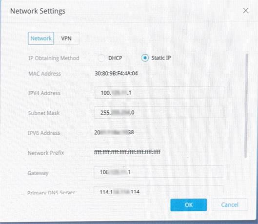
Figure 13 Static IP address configuration for backup network LAN2
4. On the Workspace client, click the configure icon in the top right corner, and then select Server Settings.
Figure 14 Selecting the Server Settings option

5. Click Add Server to add a server, or click the ![]() icon to edit an existing server. In the server configuration dialog box, enable dual network isolation, configure the IP addresses of two servers, use the default port number 8860, and then click OK.
icon to edit an existing server. In the server configuration dialog box, enable dual network isolation, configure the IP addresses of two servers, use the default port number 8860, and then click OK.
Figure 15 Adding or editing a server

Figure 16 Configuring the IP addresses of two servers

6. Select the server with dual network isolation enabled, and then click OK.
Figure 17 Selecting the server with dual network isolation enabled

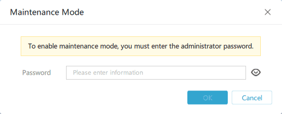
7. On the Workspace client, click the configure icon in the top right corner, and then select Maintenance Mode. In the dialog box, enter the endpoint management password (Password@1234 by default) to return to the operating system of the endpoint.
Figure 18 Selecting the maintenance mode option
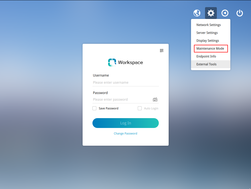
Figure 19 Entering the endpoint management password
8. On the endpoint, click the menu button in the bottom left corner and then select Preferences > Network Connections. Double-click the wired connection, click the IPv4 Settings tab, set Method to Automatic (DHCP), delete the static IP address configured for LAN1, and then click Save. Then, proceed to "Verifying the configuration."
Figure 20 Enabling DHCP for the endpoint local network connection

Configuring dual network isolation in the DHCP and static IP address allocation scenario
1. Switch the network switcher to LAN1. On the endpoint, click the menu button in the bottom left corner and then select Preferences > Network Connections. Double-click the wired connection, click the IPv4 Settings tab, and then set Method to Automatic (DHCP).
Figure 21 Enabling DHCP for the endpoint local network connection
2. Launch the Workspace client, click the configure icon in the top right corner, and then select Network Settings.
Figure 22 Selecting the Network Settings option

3. Click the Network tab, set the IP address allocation method to DHCP for the primary network and static for the backup network, configure a static IP addresses for the backup network, and then click OK.
| NOTE: The primary network is LAN1, and the secondary network is LAN2. |
Figure 23 DHCP configuration for primary network LAN1

Figure 24 Static IP address configuration for primary network LAN1

4. On the Workspace client, click the configure icon in the top right corner, and then select Server Settings.
Figure 25 Selecting the Server Settings option

5. Click Add Server to add a server, or click the ![]() icon to edit an existing server. In the server configuration dialog box, enable dual network isolation, configure the IP addresses of two servers, use the default port number 8860, and then click OK.
icon to edit an existing server. In the server configuration dialog box, enable dual network isolation, configure the IP addresses of two servers, use the default port number 8860, and then click OK.
Figure 26 Adding or editing a server
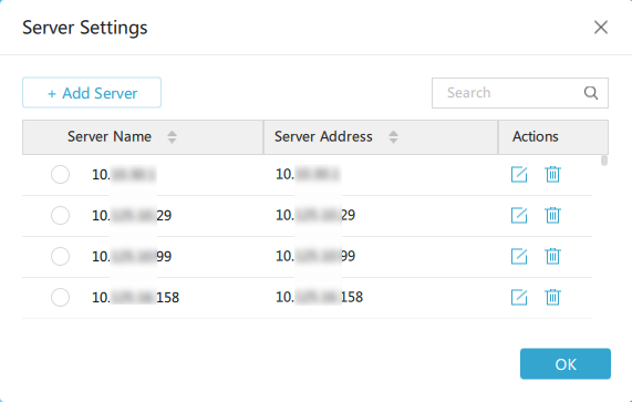
Figure 27 Configuring the IP addresses of two servers

6. Select the server with dual network isolation enabled, and then click OK. Then, proceed to "Verifying the configuration."
Verifying the configuration
After dual network isolation is configured, when the network switcher is switched, the client will automatically switch to the login page corresponding to the network.
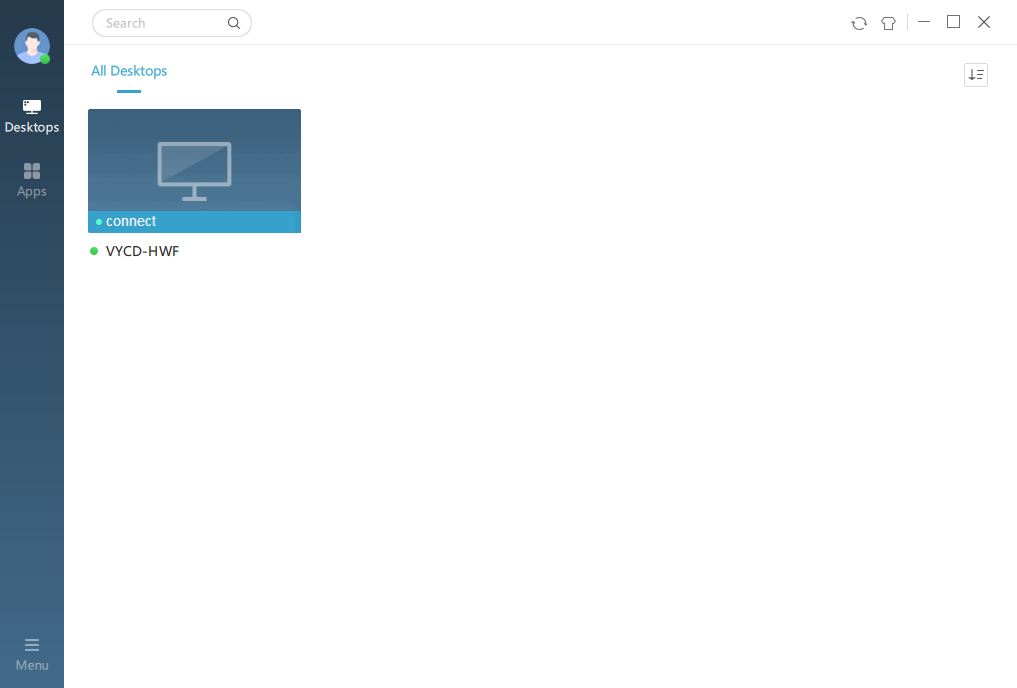
1. The endpoint is currently in the 10.125.x.x subnet of LAN1. On the client login page, enter the username and password for the server in the 10.125.x.x subnet and click Log In to view the desktop list for the 10.125.x.x subnet.
Figure 28 Connecting to the server in the 10.125.x.x subnet of LAN1
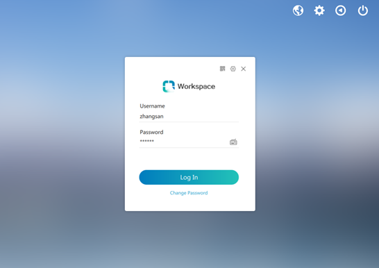
Figure 29 Desktop list for the 10.125.x.x subnet of LAN1
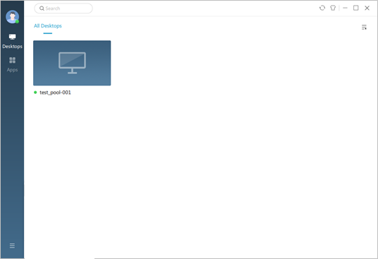
2. From the network switchover, switch the endpoint to the 10.132.x.x subnet of LAN2. The client will detect the network switchover and display the login page for the server in the 10.132.x.x subnet. Enter the username and password for the server in the 10.132.x.x subnet and click Log In to view the desktop list for the 10.132.x.x subnet.
| NOTE: The username and password before the switchover will be automatically filled in on the login page after the switchover. If the username and password are the same in both networks and automatic login is selected, the desktop list will be displayed automatically after the switcher. If the username and password are different in the dual networks, you need to enter the correct username and password. |
Figure 30 Login page for the server in the 10.132.x.x subnet of LAN2

Figure 31 Desktop list for the 10.132.x.x subnet of LAN2
Related documentation
Table 1 Related documentation
Document | Obtaining method |
H3C Workspace Cloud Desktop Client User Manual (Office Scenario) |
